
OWNER’S MANUAL

A Division of Heartland Recreational Vehicles, L.L.C
Dear Valued Customer
CONGRATULATIONS! and thank you for your business. This owner’s manual outlines the Breckenridge One Year Limited Warranty.
We encourage you to follow the Product Delivery Inspection procedures with your selling dealer. You should receive an extensive walk through and demonstration of your RV, and the warranty statement contained in this manual should be fully explained to you. The desired result is that you have been informed of the warranty provided, the operation, the maintenance required, and details of the responsibilities of the manufacturer, dealer, and retail partnership.
At Breckenridge, we want you to be able to enjoy your new recreational vehicle. In the following pages, you will learn about your warranty, the features of your Breckenridge, and the maintenance necessary to ensure years of enjoyable use. We encourage Breckenridge owners to review and pay special attention to the following:
- Warranty Statement – please read the full warranty statement.
- Weight rating – please review the proper loading, hitching and towing instructions for your safety and that of others.
- Care and Maintenance – review sealant maintenance requirements.
- Slide Room Operation – review operation instructions, maintenance, adjustments.
- LP and Appliances – review function and safety equipment provided.
- Tire and Lug Nut – review inflation and lug nut torque specifications.
- Modifications/Deviations – review which changes or alterations can void the warranty.
- Condensation – review causes and advice on how to reduce and control.
Your unit has been inspected by the factory, and received a final inspection at the dealership. Please allow your dealership to assist you in remedying any warranty issues, and should you need to contact our Elkhart, Indiana service facility, please contact us at 1-574-262-8030 / 877-262-8032
We wish you many seasons of happy camping with your Breckenridge product.
Best Regards,
The “Breckenridge Team”
Heartland Recreational Vehicles
Dealer Services - Warranty Department
2831 Dexter Drive
Elkhart, IN 46514
Ph. 574-262-8030 / 877-262-8032
|
|
This manual is based on the latest information available at the time of publication. Due to continuous product development and improvements, Breckenridge reserves the right to make changes in product specifications and components without prior notice or obligation. The most recent version of the owner’s manual can be found on our web site “www.breckenridgefinerliving.com” under the customer service heading. |

PUBLISHED MARCH 2014
REVISED JANUARY, 2015
This page left intentionally blank.
BRECKENRIDGE, A DIVISION OF HEARTLAND RECREATIONAL VEHICLES, LLC
LIMITED ONE (1) YEAR WARRANTY IN THE UNITED STATES AND CANADA
1. WHAT IS COVERED
Except as specifically excluded below, Breckenridge RV WARRANTS for a period of ONE (1) YEAR to the original retail purchaser, who purchases the recreational vehicle from an authorized Breckenridge RV dealer and who uses the recreational vehicle, under normal use, for private single family recreational travel, camping and seasonal usage, that the recreational vehicle manufactured and assembled by Breckenridge RV shall be free from defects in material and/or workmanship supplied and attributable to Breckenridge RV in the construction of the recreational vehicle. “Defect” means the failure of the unit and/or the materials used to assemble the unit to conform to Breckenridge’s design and manufacturing specifications and tolerances. Any product used for a commercial or business purpose, including, but not limited to, rental, charter, or other fees for service, or as a residence is specifically excluded from this Limited Warranty. This Limited Warranty is intended for the original retail owner and is non-transferable.
The warranty coverage starts from the date of the original retail purchase. Except as noted below this Limited Warranty covers only those defects that occur within one (1) year of the date of the original retail purchase. All obligations of Breckenridge RV pursuant to this Limited Warranty are limited to replacing or repairing the defective part or component.
2. WARRANTY DISCLAIMERS
This written limited warranty is the entire warranty authorized and offered by Breckenridge RV. There are no warranties or representations beyond those expressed in this written document. This written limited warranty cannot be amended by any dealer, sales person or agent. To the extent permitted by applicable law, all implied warranties, including the implied warranties of merchantability, fitness for a particular purpose, quality, durability, and against latent defects, are hereby disclaimed. To the extent the implied warranties cannot be disclaimed under applicable state law, all such implied warranties are limited in duration to the term of this limited warranty and are limited in scope of coverage to those portions of the unit covered by this warranty. Breckenridge RV is not responsible for any undertaking, representation or warranty made by any dealer or other person beyond those expressly set forth in this limited warranty.
The retail purchaser shall not be entitled to recover from Breckenridge RV any consequential or incidental damages resulting from any defect in the unit. The exclusion of consequential and incidental damages shall be deemed independent of, and shall survive, any failure of the essential purpose of any limited remedy.
Any action to enforce this limited warranty or any implied warranties shall not be commenced more than ninety (90) days after the expiration of the one (1) year term of this warranty.
Some states or provinces do not allow limitations on how long an implied warranty lasts, the exclusion or limitation of incidental or consequential damages, or the reduction in the statute of limitations, so the above limitation or exclusions may not apply to you.
3. WHAT ARE THE DEALER’S OBLIGATIONS
The independent Breckenridge RV dealer, by agreement with Breckenridge RV, will maintain the recreational vehicle until it is sold to the first retail customer; will perform a comprehensive pre-delivery check procedure and inspection; will repair or replace any identified defective parts; will correct identified defects in workmanship; will present the retail owner with a copy of this warranty prior to the retail owner’s entering into any written contract to purchase a recreational vehicle; and will mail to Heartland RV a warranty registration notice and the signed Limited One (1) Year Warranty.
4. WHAT ARE THE OWNER’S OBLIGATIONS
The owner is responsible for proper maintenance and cleaning of the recreational vehicle, including its exterior and interior products and components, as more particularly described in the owner’s manual and in the materials provided by the component manufacturers. Failure of any product or component caused by improper care, cleaning procedures, negligence or faulty maintenance is expressly excluded from this warranty. Notwithstanding the foregoing, for a period of ninety (90) days, minor adjustments to components, including, but not limited to, adjustments to the interior or exterior doors, LP regulator pressure, cabinet latches and TV antenna control, will be performed by the dealer free of charge to the retail customer for a period of ninety (90) days from the original retail purchaser taking possession of the unit.
It is the owner’s responsibility to use the recreational vehicle for its intended purpose as described above and to observe and comply with all proper operating practices, instructions and safety regulations listed on the safety labels or in the owner’s manual, and/or operating practices, and safety regulations required by law. Failure to comply with all rules, regulations and instructions will invalidate this Limited Warranty.
If a problem occurs which the owner thinks is covered by this Limited Warranty, the owner is responsible for contacting Heartland RV or an authorized Breckenridge RV dealer by certified mail, telephone, or e-mail giving specific notice of the problem(s) being experienced with the recreational vehicle. Such notice must be sent to Heartland RV, LLC, 2831 Dexter Drive, Elkhart, IN 46514. Heartland RV will arrange for repair or replacement parts if materials or workmanship are identified as defective by Heartland RV. The owner is advised that he/she must notify Heartland RV of any items believed to require warranty service. Heartland RV reserves the right to cure all warranty claims. Warranty work, repairs or service provided under this warranty conducted by any party not specifically authorized by Heartland, is specifically not covered by this Limited Warranty and WILL VOID THIS LIMITED WARRANTY.
The owner agrees to maintain all evidence of any defect or damage through the ultimate resolution of any claim and make such evidence available to Heartland RV and further agrees that the failure to preserve evidence will result in loss of the claim.
The owner, at his/her expense, will deliver the recreational vehicle to the dealer or authorized repair location or manufacturing plant for warranty service as designated.
5. WHAT IS NOT COVERED BY Breckenridge RVS LIMITED WARRANTY
- This Limited Warranty does not cover retail sold units for which Breckenridge RV has not received the Breckenridge RV Warranty Registration Notice.
- Additional components which have been installed in the recreational vehicle, including but not limited to microwave ovens, ranges, refrigerators, leveling jacks, furnaces/heaters, DVD/CD players, air conditioning, icemakers, vacuum cleaners, televisions, hot water heaters, generators, power converters, batteries, and other items not specifically manufactured by Breckenridge RV, are warranted by the component manufacturers as detailed in their individual manufacturers’ warranties, and are not covered by this Limited Warranty. Copies of the warranties may be found in the product owner’s packet or by contacting Heartland RV, LLC.
- Problems which may result from not following proper operating practices, instructions, warnings or regulations, including but not limited to those contained in the owners manuals, on labels or otherwise provided by law.
- Failure which may be caused by, or related to abuse, misuse, negligence, or accident, failure which may be related to alteration or modification, failure as a result of not following instructions contained in the owners manuals.
- Normal deterioration due to wear or exposure, such as fading of fabrics or drapes, carpet wear, exterior surfaces, etc.
- Maintenance items: such as light bulbs, fuses, lubricants, minor adjustments.
- Use of the recreational vehicle for any commercial or rental purpose voids the warranty from the time that the vehicle is first used for commercial or rental purposes and at all times thereafter.
- Transportation to and from dealer or manufacturing plant locations for any purpose, including but not limited to warranty purposes.
- All consequential and incidental expense such as, but not limited to, loss of time, commercial loss, loss of use, towing charges, lodging, food, phone calls, inconvenience, bus and plane fares, or rental charges.
- Any defect or shortages readily apparent on delivery to the initial retail purchaser unless noted on the delivery sheet completed by the driver transporting the RV to the independent dealer.
- Environmentally caused conditions such as rust, or sealant deterioration.
6. “ADDITIONAL IMPORTANT INFORMATION” – CUSTOMER PLEASE READ
- Please inspect your recreational vehicle at the time of delivery and make sure you accept it as delivered to you. This recreational vehicle has been sold by Breckenridge RV to an independent dealer, who is not an agent of Breckenridge RV, for resale in the ordinary course of the dealer’s business. The sale to you is by the dealer, not Breckenridge RV, on terms and conditions and equipped as the dealer and you determine, and your agreement is solely with the dealer, not Breckenridge RV. Breckenridge RV does not participate in retail sales or retail contracts in any instance, and its sole obligation is this Limited Warranty.
- Breckenridge RV reserves the unrestricted right at any time and from time to time to make changes in the design of and/or improvements upon its product without thereby imposing any obligation upon itself to make corresponding changes or improvements in or upon its products already manufactured. Breckenridge RV further reserves the right to substitute parts or components of substantially equal quality in any warranty service required by operation of this Limited Warranty.
- A recreational vehicle and the products installed in it will require care and maintenance attention by the owner and occupants. Please read and follow all care and maintenance manuals and instructions supplied with your recreational vehicle.
7. DISPUTE RESOLUTION
At the option of Heartland RV, any and all claims, demands, causes of action or disputes arising out of or relating in any way to this warranty or the recreational vehicle shall be resolved exclusively in arbitration in accordance with the Indiana Arbitration Act (IC 345711, et seq.), the Uniform Arbitration Act (IC 345722, et seq.), and the Indiana Rules for Alternative Dispute Resolution, Rules 3.1 through 3.5. There shall be one (1) arbitrator appointed by the Elkhart Circuit or Superior Court, Elkhart County, Indiana, who shall be an attorney with professional experience in the recreational vehicle industry. All costs and expenses of the arbitration will be paid by the party against whom the arbitrator rules; however, each party will bear its own attorneys’ fees.
In the event that Heartland RV does not elect to submit any dispute to arbitration or the foregoing arbitration provision is found to be unenforceable, the exclusive jurisdiction for deciding any and all claims, demands, causes of action or disputes arising out or relating in any way to this warranty or the recreational vehicle shall be the Elkhart Circuit or Superior Court, Elkhart County, State of Indiana. By executing this warranty, the retail purchaser agrees to the jurisdiction of the courts set forth above.
8. APPLICABLE LAW
The terms of Breckenridge RV’s obligations under this Limited Warranty are drafted to comply with the Magnuson-Moss Warranty Act. To the extent other laws are deemed to apply in any respect to this Limited Warranty, the law applicable to this Limited Warranty and all claims, demands, disputes, causes of action, arbitration or litigation relating to this Limited Warranty or from the sale, purchase or use of the recreational vehicle shall be the internal laws of the State of Indiana.
Breckenridge RV is not responsible for any representation or warranty that is not herein stated. Some states do not allow the exclusion or limitation of incidental or consequential damages. This warranty gives you specific legal rights. You may also have other rights that may vary from state to state, or province to province. Where any term of this warranty is prohibited by such laws, it shall be null and void, but the remainder of this warranty shall remain in full force and effect.
Date:______________
Model:________________________________ Serial No.:_____________________________
Signature:_____________________________ Signature:_____________________________
Printed:_______________________________ Printed:_____________________________
This page left intentionally blank.
Table of Contents
Dear Valued Customer1
Limited Warranty3
Reporting Safety Defects7
Owner’s Information8
Important Safety Precautions9
Key Information10
Customer Update Form13
Pre-trip Checklist15
Driving Safety16
Maintenance Schedule18
Maintenance Record21
Hitching & Loading23
Wheel Nut Torque29
Tires & Braking31
Glossary of Tire Terminology41
Leveling43
Power Systems45
Electrical System47
Fire Safety48
Gas System49
Plumbing54
Appliances58
Equipment60
Slide Outs62
Elevated Beds & Electric Bed Lift System63
Exterior Maintenance64
Interior Care66
Winter Storage67
Prolonged Occupancy68
Molds70
Chemical Sensitivity71
Reporting Safety Defects
At the time a motor vehicle manufactured on or after September 1, 1990 is delivered to the first purchaser for purposes other than resale, the manufacturer shall provide to the purchaser, in writing in the English language and not less than 10 point type, the following statement in the owner’s manual, or, if there is no owner’s manual, on a one-page document:
If you believe that your vehicle has a defect which could cause a crash or could cause injury or death, you should immediately inform the National Highway Traffic Safety Administration (NHTSA) in addition to notifying BRECKENRIDGE.
If NHTSA receives similar complaints, it may open an investigation, and if it finds that a safety defect exists in a group of vehicles, it may order a recall and remedy campaign. However, NTHSA cannot become involved in individual problems between you, your dealer, or BRECKENRIDGE.
To contact NHTSA, you may either call the Vehicle Safety Hotline toll-free at 1-888-327-4236 (TTY: 1-800-424-9153); go to http://www.safercar.gov; or write to: Administrator, NHTSA, 1200 New Jersey Avenue, S.E., Washington, DC 20590. You can also obtain other information about motor vehicle safety from
http://www.safercar.gov.
Important Owner’s safety Information
This guide has been provided by Breckenridge for the purpose of providing instructions about the operation and maintenance of this vehicle and its components. The only warranty offered by Breckenridge is set forth in the written One Year Limited Warranty that applies to this vehicle (see pp. 3-5). Nothing in this manual creates any other warranty, either expressed or implied.
Instructions are included in the manual for operating some of the components that are standard on this vehicle. Instructions may also be given for components that are options and may not appear on all vehicles. For more detailed information on the components installed, refer to the individual component manufacturer’s operating instructions contained in the Owner’s Information Package.
Breckenridge has attempted to compile the most current information available at the time this guide was published. If the components in your unit vary significantly from what is described within this manual, then consult the instructions provided by the component manufacturer found in the Owner’s Information Package.
Throughout this guide, reference is made to the following terms: Danger, Warning, Caution, and Note. These terms indicate important information that must be understood and followed. The definitions of these terms are:
|
|
|
DANGER indicates a hazardous situation which, if not avoided, will result in death or serious injury. |
 DANGER
|
|
|
WARNING indicates a hazardous situation which, if not avoided, could result in death or serious injury. |
|
|
|
CAUTION, used with the safety alert symbol, indicates a hazardous situation which, if not avoided, could result in minor or moderate injury |
|
NOTICE |
|
NOTICE is used to address practices not related to personal injury. This applies to hazardous situations involving property damage only |
|
|
Important information regarding the maintenance of your recreational vehicle. |
Very Important:
Your warranty is activated only after Breckenridge has received your signed warranty registration card from your selling dealer where it should have been signed. If you never signed this card or wish to make sure your warranty is activated, please contact your dealer or the Heartland Warranty Department at 574-262-8030 or you may inquire in writing to Heartland Recreational Vehicles, 2831 Dexter Drive, Elkhart, IN 46514.
You’ll find many safety recommendations throughout this section, and throughout this manual. The recommendations on these pages are the ones we consider to be the most important.
Do Not Allow Passengers to Ride in the Trailer During Travel
The transport of people puts their lives at risk and may be illegal. The trailer does not have seat belts, therefore, it is not designed to carry passengers.
Reducing Fishtailing or Sway
Sway or fishtailing is the sideways action of a trailer caused by external forces. Excessive sway of your travel trailer can lead to the rollover of the trailer and tow vehicle resulting in serious injury or death. Be sure to follow the instructions and warnings as outlined on page 27.
Mold
There are mold and mold spores throughout the indoor and outdoor environment. There is no practical way to eliminate all mold and mold spores in the indoor environment; the way to control indoor mold growth is to control moisture (see page 71).
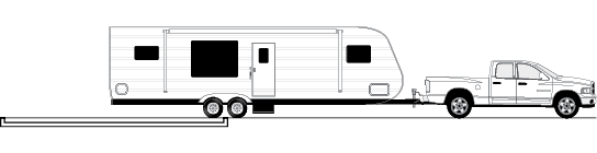
Towing and Weight Distribution
Weight distribution is an important factor when loading your travel trailer. A recreational vehicle with the cargo distributed properly will result in efficient, trouble-free towing (see page 27).
Formaldehyde
Formaldehyde is an important chemical used widely in building materials and numerous household products. It is also a by-product of combustion and certain other natural processes. Thus, it may be present inside the trailer with some individuals being sensitive to it. Ventilation of the unit normally reduces the exposure to a comfortable level (see page 72).
Lug Nut Torquing
Being sure wheel mounting nuts (lug nuts) on trailer wheels are tight and properly torqued is an important responsibility that trailer owners and users need to be familiar with and practice. Inadequate and/or inappropriate wheel nut torque (tightness) is a major reason that lug nuts loosen in service. Loose lug nuts can rapidly lead to a wheel separation with potentially serious safety consequences (see page 29).
Appliances and Equipment
The appliances (stove, refrigerator, outdoor grills, etc.) and equipment (hot water heater, furnace generator, etc.) typically operate on LP gas. LP gas is flammable and is contained under high pressure. Improper use may result in a fire and/or explosion. Be sure to follow all instructions and warnings in this manual (see pages 59-62) as well as the specific owners’ manuals of the appliances and equipment.
Tire Safety
Properly maintained tires improve the steering, stopping, traction, and load-carrying capability of your vehicle. Underinflated tires and overloaded vehicles are a major cause of tire failure. For more information on tire safety, please see pages 31-39.
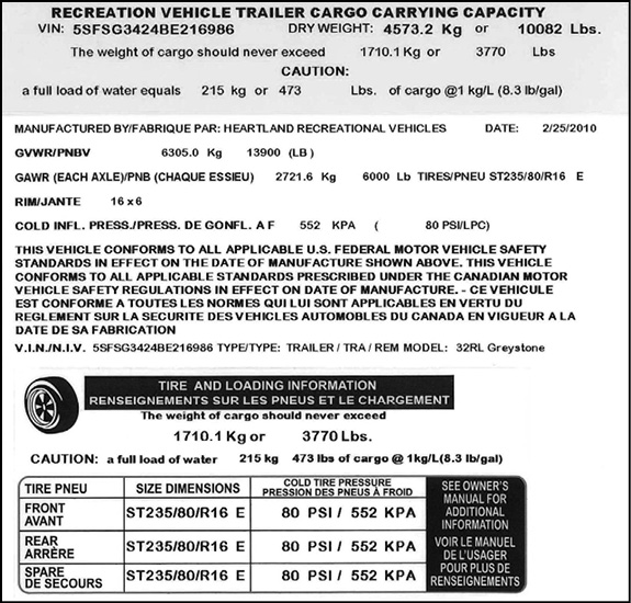
Specification Label:
There are two main numbers used to identify the vehicle. The Vehicle Identification Number (VIN) is the legal identification of the completed vehicle. The VIN is the number used by the state for vehicle registration. The Breckenridge Serial Number is a six digit number that is comprised of the last six digits of the VIN. This Breckenridge Serial Number is needed whenever making an appointment for service or ordering parts through your Breckenridge Dealer or Service Center. This number can be found on the placard at the entry door and on the Customer Care Card received from Breckenridge. Below is a sample of the placard located in the kitchen. On this Trailer Weight Rating placard you will find:
- The VIN Number
- GVWR of the unit.
- Cargo carrying capacity of the unit.
Important Facts:
If you are traveling or move, any authorized dealer, at their discretion, may provide service. Keep your warranty registration form with the vehicle at all times since it must be presented for warranty service. This form is your proof of purchase and provides the date of retail sale, both of which are necessary to determine warranty eligibility.
Important Facts:
Please inspect your recreational vehicle at the time of delivery and make sure you accept it as delivered to you. This recreational vehicle has been sold to an independent dealer, and not an agent of Breckenridge for resale in the ordinary course of the dealer’s business on terms and conditions and equipped as he and you determine and your agreement is solely with the dealer, not Breckenridge. Breckenridge does not participate in retail sales or retail contracts in any instance, other than by terms of this Limited Warranty.
Important Facts:
Using an RV in temperatures above 80 degrees or below 32 degrees Fahrenheit will require additional equipment to properly cool the RV or prevent freezing of the RV systems and components. Additional care or preventative measures should always be exercised when using an RV in extreme temperatures.
Important Facts:
Breckenridge reserves the unrestricted right at any time and from time to time to make changes in the design of and/or improvements upon its product without thereby imposing any obligation upon itself to make corresponding changes or improvements in or upon its products already manufactured. Breckenridge further reserves the right to substitute parts or components of substantially equal quality in any warranty service required by operation of this Limited Warranty.
Important Facts:
Like any other product, a recreational vehicle and the products installed in it will require care and maintenance attention by the owner and occupants. Please read and follow all care and maintenance manuals and instructions supplied with your recreational vehicle.
Key Information to have on hand (Breckenridge customer should fill out):
All warranty work needs to be completed during the term of the warranty.
Warranty beginning date: ______/______/_____ Warranty ending date: _____/_____/_____
VIN#: _________________________
Note: All service work performed after the expiration date will not be covered by Breckenridge
Original Owner:_______________________________ Phone Number:_______________
Dealership Purchased from: _____________________ Phone Number: _______________
Second Owner:_______________________________ Phone Number: _______________
Person or Dealership Purchased from:_____________ Phone Number: _______________
OUR VALUED CUSTOMERSIf, for any reason, you have a problem obtaining satisfactory and timely warranty service that may substantially impair the use, value or safety of your Breckenridge product, please call us so that we may attempt to resolve your concerns. Authorized dealers are independent contractors and independently owned businesses. This is also true of the authorized service centers. Please note, your Breckenridge warranty covers warrantable repairs that are performed by an authorized Breckenridge dealer at their service center or facility only. It is important for the owner to know that if you are unable to bring your unit in for repairs, Breckenridge is not responsible for any costs incurred for the service call charge, or time accrued to come out to your unit. Can’t find a dealer? Have an emergency? Heartland customer service can be reached at 574-262-8030/ 877-262-8032. We can help locate a dealer nearby or, in case of emergency or special circumstances, provide authorization to a local repair facility. Before using any non-authorized dealer for any warranty repair – call Heartland first! |
This page left intentionally blank.

Customer Information Update Form
Heartland strives to keep the most accurate and current customer information in its files in order to maintain good customer relations.
If you bought this unit new, we have your information from the warranty registration form which you have sent to us on file. If, however, you purchased this unit as used then we ask that you complete the following information and mail it or fax it to us at 574-262-8340 so that we can be sure that our records are updated.
Please note that the date of purchase on the card will show the original date the vehicle was first purchased and is the date applicable warranties originated. Note: the warranty on a Breckenridge coach is non-transferable. This customer information update form is for record keeping purposes only. If you have any questions, please contact a Breckenridge service representative.
DATE: _________________________ COACH VIN NO.: ___________________________
CUSTOMER FULL NAME: ___________________________________________________
CUSTOMER ADDRESS: ___________________________________________________
___________________________________________________
TELEPHONE NUMBER: ___________________________________________________
EMAIL ADDRESS: ___________________________________________________
PURCHASED FROM: ___________________________________________________
ADDRESS: ___________________________________________________
___________________________________________________
|
Breckenridge ATTN: Dealer Services/Warranty Department 2831 Dexter Drive Elkhart, IN 46514 Phone No. 574-262-8030 |
This page left intentionally blank.
(AT HOME)
Have read and understood your owner’s manual? _______
If not, please do so now.
EXTERIOR:
All objects secure _______
Awnings locked _______
Tires at proper pressure (including spare) _______
(check for wear/damage)
Wheel lug nuts tightened to proper torque _______
Hitch and/or pin box secured properly _______
All exterior lights operational _______
Battery (batteries) fully charged, fluid level okay _______
Brakes checked for operation _______
Secure cargo and lock compartment doors _______
Under-carriage items secure _______
Slide rooms are sealed tightly when closed _______
INTERIOR:
Antenna lowered _______
Roof vents lowered _______
Refrigerator locked _______
Water heater OFF _______
Water pump OFF _______
Fresh water tank level _______
Waste water tank level _______
Toilet operational _______
Furnace OFF _______
LP Gas System checked _______
Cooktop Cover CLOSED _______
Drawers, Closets, Windows CLOSED _______
Television Swivel Trays LOCKED _______
(AT CAMPSITE)
FOLLOW THE PREVIOUS CHECKLIST WITH THESE ADDED POINTS:
EXTERIOR:
Disconnect all shore lines _______
(City water, electric, sewer, cable)
Hook up tow vehicle _______
Remove wheel chocks _______
Retract step _______
Store camping equipment _______
CHECK CLEARANCES PRIOR TO PULLING OUT!
This checklist may seem like it contains basic items, but many are taken for granted and can spoil a trip if not attended to prior to moving the trailer.
You may want to use this list as a start for your own Pre-Trip checklist, which may include your personal camping gear and food preferences.
ITEMS TO CARRY:
- Local, state and national maps. Truck atlases can be useful for showing maps, refueling stations and truck repair facilities.
- An emergency road kit and flashlight.
- An assortment of spare fuses.
- An assortment of hand tools.
- 12 Volt DC test light may be helpful when speaking with a technician.
- A battery hydrometer to check the condition of battery electrolyte.
- Polarity tester to check 120 AC outlets.
- Potable/non-potable water hoses and a water pressure regulator.
Towing a recreational vehicle may be a new experience for you. Find out what gears are right for your vehicle. For sharp turns, reduce your speed and swing wide after considering other traffic and obstacles in the intersection. Proper braking is extremely important for safety. The total weight being towed is much greater than a car, so it is important to anticipate traffic signals, stop signs and other traffic. Decelerate slowly, whenever possible, to prevent undue wear on brakes and tires. When passing a semi, bus or other large vehicle from either direction, air turbulence may cause the RV to sway slightly. Improper use of a recreational vehicle may cause physical damage and/or personal injury to the vehicle operator, occupants and others. Other precautions include:
- Never exceed posted speed limit; reduce speed when required by weather, traffic or road conditions.
- Use extreme caution when going downhill. Excessive speed may cause loss of control.
- Never attempt to pass on a curve or anywhere the view of the road ahead is restricted.
- Always check recreational vehicle brakes, lights and breakaway switch before starting out on a long trip. Confirm that brakes are applied evenly. Uneven braking will pull the trailer to one side, which may cause a loss of control when towing.
|
|
|
DO NOT RIDE OR ALLOW OTHERS TO RIDE INSIDE THE recreational vehicle WHILE IT IS BEING TOWED. Seat belts are not provided and transporting of individuals and pets could result in death or serious injuries of them. |
 WARNING
Tow Vehicle
It is important that the recreational vehicle is matched with an appropriate tow vehicle. A tow vehicle with an inadequate gross combined weight rating (GCWR) may experience mechanical failures and may not provide adequate towing stability. Consult your dealer for help in selecting the vehicle hitch and related hitching accessories.
Tips For Driving
Due to the overall vehicle length, the turning radius is much wider than a standard automobile. Always pay close attention to the perimeters: front, sides, rear, roof and undercarriage- Make sure the surrounding area is clear of any obstacles. Swerves and sharp turns, especially performed at high speeds, could result in the loss of control of the vehicle. Drive with extra caution to avoid situations which might require quick momentum changes. When passing another vehicle, allow extra time and space due to the additional length and weight. Practice using the brakes away from traffic to get the feel of the distance required to stop the vehicle.
When traveling, make sure bridges can support the combined weight of the tow vehicle and recreational vehicle. Tonnage limits for bridges should be posted at entrances. Also, check the posted height of overhead clearances. Keep in mind road surfaces may have been repaved or become packed with snow. Therefore, the actual posted clearance height may not apply.
If a problem occurs, do not panic. If a sudden bumping or fish-tailing occurs, it may indicate a flat tire. Do not jam on the brakes or suddenly accelerate in an attempt to drive out of it. Instead, come to a stop slowly while driving as straight as possible. If conditions permit, coast to a very slow speed and try to avoid braking, except when the wheels are straight ahead and the trailer and tow vehicle are in line with each other.
If the vehicle begins to fishtail when accelerated to highway speed, back off the accelerator. This should stop the fish-tailing. If it begins again when speed increases, stop and check the load, which may not be distributed evenly from side to side, or is too far back to put a sufficient load on the hitch pin. Redistribute the load, as necessary, before continuing.
Driving Cautions:
- Avoid getting to close to the edge of the road, a soft shoulder may not support the weight of the vehicle.
- Driving lanes in work zones can be uneven, congested and more narrow than usual.
- Be cautious of road debris which can damage the undercarriage of the vehicle or cause damage to the tires or wheel rims.
- Keep in consideration that posted speed signs are for passenger automobiles. Therefore, use extra awareness of the driving conditions and an appropriate speed for a vehicle with trailer, especially on corners and mountain roads.
- Downgrade speed should be at least 5 mph less than upgrade speed, or downgrade speed should be attainable within three seconds of a brake application.
|
NOTICE |
|
TOWING ANYTHING BEHIND YOUR RV COULD CAUSE DAMAGE TO THE FRAME AND WILL VOID YOUR FRAMES WARRANTY. |
Right Turns
Negotiating a right-hand turn while pulling a recreational vehicle can be difficult, but can be negotiated well using these tips:
- As the turn approaches, look into the mirror to ensure the lane to the left is clear, then move wide over to the left.
- Make the turn slowly.
- Check mirrors frequently. Be aware of necessary clearance and space management for the trailer while turning.
Night Driving
- Be well rested and alert when driving. If necessary, find a safe stopping place to rest until you are ready to continue.
- Avoid using any interior lights while driving. They can create a glare on the windshield decreasing visibility.
- Dim dash lights to a comfortable level to reduce glare.
Extreme Heat and Hot Weather Conditions
Check tire pressure frequently when traveling in hot conditions. Tire air pressure increases with heat. Do not let air out of a hot tire. When the tires cool down they return to the previous tire pressure.
Winter and Cold Climate Conditions
- Keep speeds slow and steady; make moves gradually and increase the visual distance for a gain in reaction time.
- If the road or weather conditions are treacherous, find a safe stopping place and wait for conditions to improve.
- Remove ice from the entry step to avoid slipping.
Wet Conditions:
- The risk of hydroplaning is increased if tires are worn or improperly inflated.
- Heavy rain or standing water can affect brake application.
Refueling:
- Be aware of the fuel port location on the tow vehicle. There may not be adequate space to turn around in the parking lot in order to reposition for the pump.
- Check overhead clearance before pulling through the fuel island.
- Be aware of the concrete/steel posts installed around the fuel island.
- Avoid running over the fuel hose as it can get caught and cause damage to the tow vehicle or recreational vehicle.
|
|
|
Avoid the risk of fire or explosion. Turn off all pilot lights and appliances before refueling. |
Emergencies:
If an emergency situation occurs, use the appropriate braking technique and pull off the roadway a safe distance from traffic if possible. Set the parking brake and turn on the hazard warning flashers, especially when parked alongside traffic lanes.
An emergency road kit should include at least three reflective warning signs, road flares, a flashlight, spare automotive fuses and an assortment of hand tools. The recreational vehicle is equipped with a fire extinguisher inside, near the entry door. Display road flares or reflective warning signs if the vehicle is along the road for any length of time. Guidelines for placing the warning triangles depend upon the road characteristics and visibility. The standard placement is 10’, 100’ and 200’ from the rear of the recreational vehicle when on a divided highway or one-way road. On a two-way road with traffic traveling both directions the same placement would also be required at the front of the recreational vehicle. Roads with curves and hills may require placing warnings 500’ behind the vehicle in order to safely warn approaching traffic.
|
MAINTENANCE SCHEDULE |
||||||
|
*Tighten wheel bolts or nuts every 50 miles for the first 200 miles & after every change in wheel mounting. (Torque to 120-125 ft.-lbs.) Adjust brakes after first 200 miles then at above listed intervals |
INSPECT/TEST BEFORE EACH TRIP |
MONTHLY |
EVERY 3 MONTHS |
EVERY 6 MONTHS |
YEARLY |
AS REQUIRED BY MANUFACTURER |
|
Air pressure |
X |
|||||
|
Wheel rims |
X |
|||||
|
Brake shoes |
X |
X |
X |
|||
|
Brake magnets |
X |
X |
X |
X |
||
|
Wheel bearings and cups |
X |
X |
X |
|||
|
Hub drum |
X |
X |
X |
|||
|
Seals |
X |
X |
X |
|||
|
Air pressure (best to check daily) |
X |
|||||
|
*Lug bolts or nuts |
X |
|||||
|
*Safety chains |
X |
X |
||||
|
Other: |
||||||
|
|
||||||
|
|
||||||
|
|
||||||
|
|
||||||
|
|
||||||
|
|
||||||
|
|
||||||
|
|
||||||
|
|
||||||
|
|
||||||
|
|
||||||
|
|
||||||
|
|
||||||
|
|
||||||
|
|
||||||
|
|
||||||
|
|
||||||
|
|
||||||
|
|
||||||
|
|
||||||
|
|
||||||
This page left intentionally blank.
Maintenance Record
ROUTINE MAINTENANCE
All routine maintenance is the responsibility of the owner and is not covered by the Breckenridge Limited Warranty. Use the maintenance record to record all performed maintenance as required. Please note that damage caused by improper or un-applied maintenance is not covered by the Breckenridge Limited Warranty. Use and conditions may dictate more frequent maintenance than suggested.
Items supplied by other manufacturers may require specific individual maintenance not listed herein. Please refer to the manufacturers’ suggested maintenance guidelines in the Owner’s Information Packet.
IMPORTANT: All adjustments and alignments within the first three (3) months from date of original purchase are subject to warranty coverage. Thereafter, these items are considered routine maintenance.
|
Date |
Miles |
Description Of Service Work Performed |
Service Performed By |
Cost |
|
|
|
|||||
|
|
|||||
|
|
|||||
|
|
|||||
|
|
|||||
|
|
|||||
|
|
|||||
|
|
|||||
|
|
|||||
|
|
|||||
|
|
|||||
|
|
|||||
|
|
|||||
|
|
|||||
|
|
|||||
|
|
|||||
|
|
|||||
|
|
|||||
|
|
|||||
|
|
|||||
|
|
|||||
|
|
|||||
|
|
|||||
Maintenance Record
|
Date |
Miles |
Description Of Service Work Performed |
Service Performed By |
Cost |
|
|
|
|||||
|
|
|||||
|
|
|||||
|
|
|||||
|
|
|||||
|
|
|||||
|
|
|||||
|
|
|||||
|
|
|||||
|
|
|||||
|
|
|||||
|
|
|||||
|
|
|||||
|
|
|||||
|
|
|||||
|
|
|||||
|
|
|||||
|
|
|||||
|
|
|||||
|
|
|||||
|
|
|||||
|
|
|||||
|
|
|||||
|
|
|||||
|
|
|||||
|
|
|||||
|
|
|||||
|
|
|||||
|
|
|||||
|
|
|||||
|
|
|||||
|
|
|||||
|
|
|||||
|
|
|||||
|
|
|||||
|
|
|||||
|
|
|||||
|
|
|||||
|
|
|||||
Hitches
You should become comfortable hooking up your vehicle with practice. There are several types of vehicle hitches available. Be certain to use the one recommended by your tow vehicle manufacturer and that meets the weight requirements of your vehicle. Those described here are typical, but have your dealer demonstrate and explain the proper hitching and unhitching procedure for your vehicle.
|
|
|
An improperly coupled trailer or 5th wheel can result in death or serious injury. Use of a tow vehicle with a towing capacity less than the load rating of the trailer can result in loss of control, and may lead to death or serious injury. |
 Warning
Be sure your hitch and tow vehicle are rated for the Gross Vehicle Weight Rating (GVWR) of your vehicle. Be sure the hitch load rating is equal to or greater than the load rating of the coupler. Be sure the hitch size matches the coupler size. Observe the hitch for wear, corrosion and cracks before coupling. Replace worn, corroded or cracked hitch components before coupling the RV to the tow vehicle. Be sure the hitch components are tight before coupling the RV to the tow vehicle.
Hitching A Travel Trailer
- Crank the tongue of the trailer jack up until the hitch coupler is high enough to clear the tow vehicle.
- Back the tow vehicle to the trailer until the hitch ball is directly under the coupler on the trailer.
- Set the parking brakes, raise the locking latch on the coupler and crank it down on the ball.
- Move the locking latch down to lock it on the ball.
- Engage the lock and the retainer clip.
- Raise the tongue by cranking the jack down. The tow vehicle will come up with it if the high coupler is properly attached.
- Fasten safety chains to frame of the tow vehicle. Do not fasten chains to any part of the hitch unless the hitch has holes or loops specifically for that purpose. Cross chains underneath the hitch and coupler with enough slack to permit turning and to hold tongue up, if the trailer comes loose.
- Connect the breakaway switch cable to the tow vehicle, making sure it is not attached to any part of the trailer.
- Crank the jack all the way up.
- Install and adjust side mirrors.
- Check all lights on trailer and tow vehicle.
- Pull forward and check the operation of the trailer brakes with hand control to assure proper operation. (Refer to manufacturer specifications on setting the brake control.)
If aftermarket equalizer hitch bars are attached, see manufacturer’s instructions.
|
|
|
IMPROPER RIGGING OF THE SAFETY CHAINS CAN RESULT IN LOSS OF CONTROL OF THE TRAILER AND TOW VEHICLE, LEADING TO DEATH OR SERIOUS INJURY, IF THE TRAILER UNCOUPLES FROM THE TOW VEHICLE. |
|
|
|
DO NOT CONNECT THE BREAKAWAY SWITCH LANYARD TO THE HITCH BALL OR ANY REMOVABLE PART OF THE HITCH. Failure to do so may result in damage to the cable compromising the emergency braking system. |
Always use safety chains when towing. They maintain the ball connection between the trailer and tow vehicle in the event of separation of the ball and trailer coupling. Safety chains are included with every travel trailer and, in most states, are required when towing a travel trailer. Attach chain to the designated wing areas on the right and left of the hitch ball, crossing under the trailer’s tongue. Inspect the length of the chains once attached to the tow vehicle frame. They should be long enough to allow for turns, but short enough to avoid any drag.
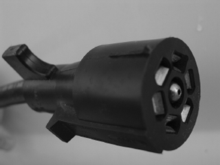
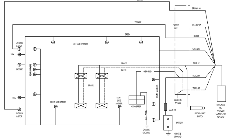
Electrical Connection
Plug the pigtail on the vehicle into the electrical harness on the truck. Be sure there is enough slack to allow the vehicle to turn without disconnecting the pigtail. Make sure all lights and the brakes work prior to moving the vehicle. Current draw should not exceed ten amps for each designated light circuit. The tow harness wires are coded as follows:
1. White, 8 gauge – Ground
2. Blue, 12 gauge – Brake
3. Green, 14 gauge – Clearance Lights
4. Black, 14 gauge – Charge Line
5. Red, 14 gauge – Left Turn
6. Brown, 14 gauge – Right Turn
7. Yellow, 14 gauge – Aux

Typical Wiring Diagram for Seven-Way Plug
|
NOTice |
|
While it is possible to operate 12V items in the RV through a tow vehicle charge line, it is not recommended due to the high power consumption of some items. |
|
notice |
|
DO NOT USE THE BREAKAWAY SWITCH AS A PARKING BRAKE, AS IT IS INTENDED FOR EMERGENCY USE ONLY AND SUCH USE WILL DRAIN YOUR RV BATTERY. |
SAFETY BREAK-AWAY SWITCH WILL NOT OPERATEunless connected to a power source equivalent to or greater than an automotive type 12 volt, 12 amp hour wetcell battery. |
|
|
|
NEVER OVERLOAD YOUR 5TH WHEEL. DO NOT EXCEED THE RATED LOAD OF THE RV OR THE RATED LOAD OF ANY AXLE! OVERLOADING CAN CAUSE LOSS OF CONTROL OF THE UNIT, WHICH CAN RESULT IN SEVERE PERSONAL INJURY OR DEATH. OVERLOADING CAN ALSO CAUSE PROPERTY DAMAGE TO THE UNIT, ITS CONTENTS AND THE TOW VEHICLE. |
Dangers of Overloading
During the design and development of our vehicles, the number and size of storage compartments and the liquid tank capacities are maximized for value and convenience. However, be mindful that if all holding tanks are filled to capacity, and all storage compartments and cupboards are filled to the maximum volume, the vehicle could be overloaded causing an unsafe condition. Refer to the manufacturer’s labels posted inside and outside of the unit for weight information.
|
notice |
|
UNDER NO CIRCUMSTANCES SHOULD THE ENGINE OF YOUR TOW VEHICLE BE ALLOWED TO “LUG” OR PULL HARD FOR EXTENDED PERIODS OF TIME. SUCH MISUSE CAN CAUSE ENGINE FAILURE. |
In addition to causing premature wear, overloading can cause problems in the area of handling characteristics. An overloaded vehicle will take longer (time and distance) to stop in an emergency. Overloading can also cause added wear to components such as tires and wheel bearings. Overloading can also cause overheating of the tow vehicle in some instances.
To avoid overloading, you must be aware of your vehicle weight situation at all times. Know where you stand when it comes to GVWR, GAWR and your current GVW AND UVW. The following is a key to understanding these terms:
Gross Vehicle Weight Rating (GVWR): is the maximum permissible weight of this trailer when fully loaded. It includes all weight at the trailer axle(s) and tongue or pin.
Unloaded Vehicle Weight (UVW): is the weight of this trailer as manufactured at the factory. It includes all weight at the trailer axle(s) and tongue or pin. If applicable it also includes full generator fluids, including fuel, engine oil and coolants.
Cargo Carrying Capacity (CCC): U.S. - Equal to the GVWR minus the UVW and LP gas weight. (Water is considered a component of cargo) Canada - Equal to GVWR minus the UVW, full fresh (potable) water weight (including the water heater) and full LP gas weight.
Gross Axle Weight Rating (GAWR): is the value specified as the load carrying capacity of a single axle system, as measured at the tire-ground interfaces.
Gross Vehicle Weight (GVW): is the weight of the coach with all the items and supplies that are loaded into the unit at any point in time.
Weighing your vehicle
First, locate a scale that will be large enough to weigh your trailer and tow vehicle. They are generally available at truck stops, concrete yards and grain elevators.
Before weighing your trailer, fill the propane tanks (80% capacity) and the fresh water tank if you plan on taking fresh water with you. Your tow vehicle should have a full tank of fuel and have all passengers included with the tow vehicle weight.
Pull onto the scales and locate the trailer in the center of the scale. block the wheels and unhitch the trailer making sure tongue jack or landing gears are set to level the trailer. Record the weight of the recreational trailer.
Hitch the trailer, raise the jacks and weigh both the trailer and the tow vehicle together. Record this weight.
Pull forward until tow vehicle is off the scales, then weigh trailer with axles on the scale. Record this weight. Subtract this weight from the trailer weight to find the hitch weight.
The Gross Vehicle Weight Rating (from the weight label) minus the recreational trailer weight equals the amount of supplies and personal gear you can carry.
If you have dual axles, you can get a weight for each axle by stopping on the scale with one axle on the scale and the other off. Record the weight of the one axle. Then move the trailer so that both of the axles are on the scale. Record this weight. The difference between the two axles will be the second axle’s weight.

It is equally important that the load is distributed evenly among all of the axles and wheels. One axle or wheel may be overloaded even if the GVWR and GAWR weights are within limits.
Pull the trailer forward until the front axle is off of the scale. On tandem axle trailers, both axles should be carrying about the same load. If not, level the trailer or redistribute the load.
 Also, check weight distribution at each wheel. Use the above technique weighing only the right or left side. Calculate the weight at each wheel. Be sure that no one wheel is overloaded. If you have trouble calculating or interpreting the weights, contact your dealer or vehicle manufacturer.\
Weight Rating
Located on the unit’s front roadside lower corner is a Federal Certification Label. This label gives the maximum weight carrying capacities of your unit and for each axle designated by the letters “GVWR” and “GAWR” respectively. The serial number of your unit is located on this label, also. Here is a sample label:
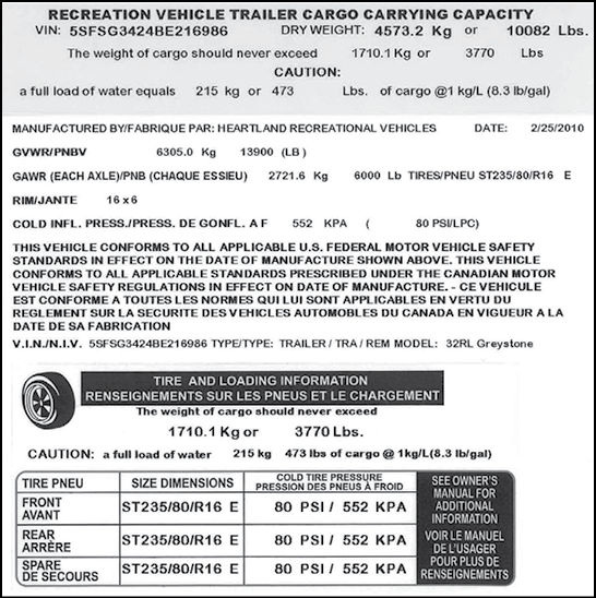
Under no circumstances should the respective loads ever exceed these ratings. Dealer installed equipment will reduce CCC. If the loaded weight of your RV exceeds the GVWR or the weight of any axle exceeds that axle’s GAWR, the RV is overloaded and you must remove items to bring the weight down to or below the GVWR or GAWR.
Tongue Weight
To determine the pin weight of the vehicle, you must weigh the tow vehicle with the trailer hitched. Record this weight. Then disconnect the trailer and weigh the tow vehicle again. Subtract the difference between the two weights and you will arrive at your pin/hitch weight. Adjust your cargo accordingly to remain within (10-15% on a Travel Trailer). The GVWR is the GAWR added to the pin/hitch weight.
Loading Instructions
Whether you start out for a weekend jaunt or a longer trip, the first thing you are going to do is load such items as food, clothing, bedding and recreational equipment. As you become experienced in RV living, you will learn what is necessary and what merely takes up storage space.
|
notice |
|
EMPTY ALL HOLDING TANKS BEFORE FILLING FRESH WATER TANK; OTHERWISE YOU WILL LIMIT CARGO CAPACITY. MOST CAMPGROUNDS SUPPLY DUMP STATIONS WHICH CAN BE UTILIZED. |
Loading Tips
After you have determined how much weight you can safely carry and selected those items to make up that weight, make a list and keep it for future reference. Load the RV and distribute the load so that you get proper weight on the axles and hitch. Do not load upper cabinets with heavy items which can shift or fall during transit. Secure and brace items so they won’t move during travel, thereby shifting the load in the RV. Do not load heavy items near either end of the RV or on the rear bumper. Adjust cargo storage to keep the side to side wheel loads as equal as possible. Carry only as much water as needed for travel use or to balance the load. Always empty your waste water and sewage holding tanks before traveling.
Make a loading diagram of your properly loaded RV. It will help you locate where specific items are stored and will help speed the loading process. Store emergency items in a readily accessible location. Include tools, first-aid kit, rain gear, flashlight, highway warning devices, and an electric cord or light.
All items must be considered for their weight and stored according to how heavy they are. Heavy items should be placed close to the floor and in the center of the vehicle. DON’T FORGET TO INCLUDE THE ITEMS YOU PURCHASE ON YOUR TRIP.
Luggage and similar cargo carried inside the vehicle must be secured to prevent possible damage in the case of a sudden stop or accident.
The amount and placement of cargo will also affect the amount of water and LP gas that you can carry. Water weighs 8.3 pounds per gallon and propane weighs 4.2 pounds per gallon. Periodically reweigh your unit. Different traveling configurations may change your loading and weight pattern.
Traveling (if applicable)
Towing – A good way to practice towing is to choose a large parking lot (where it is permissible).
Easing to a stop and starting smoothly saves wear and tear on your tow vehicle, saves gas, and prevents damage to the hitch and items stowed in the trailer. Remember, when towing the trailer, always maintain at least three cars and a trailer (approximately 85 ft) length space between you and the car in front of you for every 10 miles of speed that you are traveling. This should give you ample time to stop in case of emergency.
As you drive, try to anticipate problems that may occur and prepare for them, even though they may never happen. Anticipate dips, gutters and depressions in the street, slowing down well in advance, as these are the hardest jolts of any kind on your tow vehicle, your hitch, your trailer and items stored in your trailer. Take dips and bumps slowly and be certain that the trailer wheels have passed the point before accelerating. Cross railroad tracks slowly. Always release your brakes before crossing. On long grades, shift into a lower gear (or lower range, if you have automatic transmission) before your engine labors.
When going downhill, use the same procedure as going uphill well in advance; the compression of your tow vehicle’s engine will help to slow your whole rig safely. Avoid conditions that require excessive and prolonged use of your brakes. Apply and release brakes at short intervals to give them a chance to cool.
Controlling Sway or Fishtailing
Sway or fishtailing is the sideways action of a trailer caused by external forces. It is common for travel trailers to sway in response to strong winds or crosswinds or when passed by or passing a semi-tractor and trailer or driving downhill.
|
|
|
Excessive sway or fishtailing of your travel trailer can lead to the rollover of the trailer and tow vehicle. Serious injury or death can occur. It is important that you read and understand the information in this section. |
Sway or fishtailing of your recreation vehicle can be controlled and is primarily impacted by four factors:
- Equipment
- Tongue weight
- Driving
- Corrective measures
Equipment – When hitched together, the trailer and the tow vehicle must be level. The tires of both the trailer and tow vehicle should be in good condition and inflated to the pressure recommended as noted on the exterior of the trailer and in the owner’s manuals of the trailer and tow vehicle.
Your trailer brakes should work in synchronization with your tow vehicle brakes. Never use your tow vehicle or trailer brakes alone to stop the combined load. Your brake controller must be set up according to the manufacturer’s specifications to ensure proper synchronization between the tow vehicle and the trailer. Additionally, you may have to make small adjustments occasionally to accommodate changing loads and driving conditions.
Also, we recommend a hitch with built-in sway control be provided for your unit. Please consult your dealer regarding this equipment, as the RV manufacturer does not provide sway control devices.
Tongue weight – The tongue weight should be between 10% to 15% of the total travel trailer weight. See page 25 of this manual regarding the proper weight distribution of your recreation vehicle.
Driving – This is the most important component. The tendency for the vehicle to sway increases with speed therefore, obey all speed limits and reduce speed during inclement weather or windy conditions.
Corrective measures – If sway occurs the following techniques should be used:
- Slow down immediately, remove your foot from the accelerator. Avoid using the tow vehicle brakes unless there is a danger of collision. Reduce speed gradually whenever possible. If you can do so safely, use the brake hand controller (independent of the tow vehicle brakes) to gently and progressively apply the trailer brakes. This will help to keep the vehicles aligned. Practice using the brake hand controller on a deserted parking lot. Don’t wait until an emergency occurs before using it.
Location of the brake hand controller is important and should be made easily accessible.
- Steer as little as possible while maintaining control of the vehicle. Because of natural reaction lag time, quick steering movements to counter trailer sway will actually cause increased sway and loss of control. Keep both hands on the wheel. Hold the wheel as straight as possible until stability is regained.
- Do not jam on the brakes or attempt to press on the accelerator to speed your way out of the fishtailing. Both actions make the situation worse and could cause severe injury or death.
- Once the swaying is under control, stop as soon as possible. Check tire pressures, cargo weight distribution and look for any signs of mechanical failure. Travel at reduced speeds that permit full control until the problem can be identified and corrected.
Turning Corners
Here’s where you find the first basic difference with a trailer. The trailer wheels do not follow the path of your tow vehicle’s wheels. The trailer will make a closer turn than the tow vehicle. Compensating for the action when making turns, you will put the tow vehicle out further into the intersection than you would normally, so that the trailer will clear the curb or clear any parked vehicles along the curb. Making a left turn requires a technique similar to a right turn, with a wider than normal swing into the new lane of traffic to keep the trailer from edging into the opposing lane.
On sharply winding and narrow roads keep well to the center of your lane, equally away from both the center line and the pavement edge. This allows the trailer to clear the edge of the pavement without likelihood of the wheels dropping off onto the shoulder, which could cause dangerous trailer sway. Do not overcrowd or cross the center line. All sharp turns should be taken at low speeds. Professional drivers, when rounding turns, slow down well in advance of the turn, enter it at reduced speed, and then accelerate smoothly as they come out again onto the straightaway.
Overtaking and Passing
When you pass another vehicle, remember that it takes longer to accelerate and you must allow for the length of the trailer to pass as well, before returning to your lane. Use your signals freely. On freeways and expressways, try to pick the lane in which you want to move and stay in it, preferably the slow lane to the right. Remember, always pass very carefully.
Slippery Pavement
On slippery and icy pavement, drive slowly, and if you feel you are skidding, gently apply the trailer brakes only.
Backing and Parking
After arriving at your destination, your next task is to choose a good level parking space and back into it. A recommended procedure for backing into a space is:
Stop near the site, get out and look it over. (Check the site for low hanging tree limbs, posts, large rocks, etc., which are to be avoided.)
Always try to place the site to your left. This way you can see what the trailer is doing while you are backing. If the site is on your right, you will be backing onto your blind side, which is more difficult.
With everything clear, maneuver the vehicle into position for backing into the site.
Now grasp the steering wheel at the bottom (never at the top) and back up. Turn the steering wheel in the direction you wish the vehicle to go. If the site is on your left, move your hand to the left and back slowly, watching the vehicle. When the vehicle starts into the turn, follow it by easing up on the steering wheel. The vehicle will move into position.
Once in site, pull vehicle forward & back again to prevent trailer from maintaining a binded position which can damage the trailer and components.
Proper wheel nut torque is essential to safe and dependable trailering. The wheel and axle systems used in RVs are similar in many ways to those used in cars and trucks, but they differ in several important ways. These differences require special attention to wheel nut torque both while the trailer is new and throughout the trailer’s life
Trailer wheels must carry much higher loads per wheel than passenger car or truck wheels. Furthermore, wheels on tandem axle trailers do not steer, and are subjected to very high side load stress whenever the trailer makes a tight turn. When you go around corners – especially slow, tight ones – the wheels on your trailer are subjected to these strong side loads. This tends to flex the wheel and gradually loosen the wheel nuts. Although the materials and manufacturing methods are maximized for this kind of service, these extra load stresses and flexing can cause loosening.
It is critical that the wheels be properly torqued at the start of the trip and every 50 miles for the first 500 miles of road operation. Although the wheels have been properly torqued before leaving the manufacturing plant, settling and wearing in of components during the first few miles of operation may cause some loosening of the wheel nuts.
The wheel nut torque is 90 ft-lbs. Always use an accurate torque wrench to tighten wheel nuts. A torque wrench with adequate accuracy is available at most automotive tool stores. Considering the overall investment in the trailer, this is a very reasonable cost. Use of a torque wrench can also reduce the effort required to tighten the wheel nuts.
|
|
|
IT IS IMPORTANT TO MAINTAIN PROPER TORQUE TO PROVIDE SAFE AND SECURE ATTACHMENT OF THE WHEEL TO THE HUB/DRUM. BE SURE TO USE WHEEL NUTS THAT ARE COMPATIBLE WITH THE COIN IN THE WHEEL. IMPROPERLY TORQUED WHEEL NUTS CAN CAUSE THE WHEEL TO SEPARATE FROM THE WHEEL MOUNTING SURFACE DURING OPEARTION. THIS COULD RESULT IN PROPERTY DAMAGE, SERIOUS PERSONAL INJURY, OR LOSS OF LIFE. |
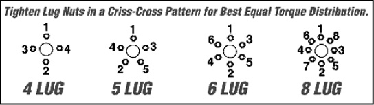
Any time a wheel is replaced, be sure to tighten the wheel nuts, following the sequence shown in the diagram to the specified torque. If the wheel was replaced, check the torque again at every 50 miles for the first 500 miles and prior to each trip thereafter. If you notice wheel wobbling or hear a rattling sound coming from a wheel, especially at low speeds, a wheel lug nut may have come loose. This problem is usually caused by improper tightening or by faulty or damaged lug bolt threads. If you have reason to believe a lug nut has come loose, SAFELY STOP THE VEHICLE AT THE SIDE OF THE ROAD AS SOON AS POSSIBLE. Put up warning devices. Remove the lug caps and check the tightness of all the lug nuts.
Tighten all lug nuts to the specified torque of 90 ft-lbs. If lug bolt threads are damaged or faulty, get professional service help. Do NOT tow the trailer with missing lug nuts or faulty lug bolts.
|
|
|
DO NOT USE A SIZE AND TYPE OF TIRE AND WHEEL OTHER THAN THAT ORIGINALLY PROVIDED BY Breckenridge BECAUSE IT CAN AFFECT THE SAFETY AND PERFORMANCE OF YOUR VEHICLE, WHICH COULD RESULT IN AN INCREASED RISE OF LOSS OF VEHICLE CONTROL, VEHICLE ROLLOVER AND/OR SERIOUS PERSONAL INJURY OR DEATH. THE INSTALLATION OF INCORRECT WHEELS COULD CAUSE WHEEL SEPARATION WHICH COULD RESULT IN PROPERTY DAMAGE, SERIOUS PERSONAL INJURY, OR LOSS OF LIFE. |
- Clean mounting surfaces, lug nuts & studs. Do no lube lug joint unless instructed in your owner’s manual.
- Start all lug nuts by hand to prevent cross threading.
- Tighten nuts in sequence shown below using a calibrated torque wrench. Do not use an impact wrench. Wheel nut torque requirements vary depending on the size and manufacturer. Always use wheel manufacturer’s recommendations
- Wheel nuts should be torqued before first road use and after each wheel removal. Periodically check and re-torque per manufacturer’s recommendations.
|
|
|
do not tow the trailer with missing lug nuts or faulty lug bolts |
Before each trip and any time a wheel is replaced, be sure to tighten the wheel nuts, following the sequence shown in the relevant lug pattern below. Set the torque specification in three stages as seen in the chart below. If the wheel was replaced, check the torque every 50 miles of the first 200 miles of travel.
If you notice wheel wobbling or hear a rattling sound coming from a wheel, especially at low speeds, a wheel lug nut may have come loose. This problem is usually caused by improper tightening or by faulty or damaged lug bolt threads. If you have a reason to believe a lug nut has come loose, safely stop the vehicle at the side of the road as soon as possible. Put up warming devices. Remove the lug caps and check the tightness of all the lug nuts. Tighten all lug nuts to the specified torque, using a torque wrench. If lug stud threads are damaged or faulty, get professional service help.
|
|
|
WHEEL SEPARATION CAN OCCUR
AR0062 |
Wheel Compatibility
|
|
|
Do NOT Missmatch Wheels and tires |
Axle systems are installed with hubs and drums that are compatible with many wheels used in the recreational vehicle industry that have matching bolt patterns. If the original manufacturer installed equipment is in need of replacement, the wheel manufacturer should be contacted for proof of compatibility prior to replacement and use.
Customers replacing original equipment that has not been tested for compatibility must ensure the replacements are compatible to the hub and drum assembly installed. Such elements of compatibility include, but are not limited to:
- Diameter of the hub-mounting surface.
- Stud length and diameter.
- Location and number of studs.
- Center hold diameter for the wheel.
- Wheel mounting offset from the rim center.
- Rated capacity of the wheel.
- Wheel fastener torque.
- Wheel nut size and shape.
Impact of any added wheel accessories (such as decorative center caps) that could affect proper seating of the wheel to the hub surface.
Certain tests are recommended by the manufacturer’s of factory installed equipment, such as the cornering fatigue test based on SAE J1095/SAE J267 and field tests, are recommended for all wheels and rims to be installed in place of original factory equipment. Contact the wheel manufacturer to verify compatibility with the factory installed equipment prior to replacement.
Tire Inspection
The following chart is meant to be helpful in determining the condition and maintenance of your tires:
|
Condition |
Possible Cause |
Remedy |
|
|
|
Even Center Wear |
Over Inflation |
Check & Adjust Pressure When Cold |
|
|
Inside & Outside Wear |
Under Inflation |
Check & Adjust Pressure When Cold |
|
|
Smooth Side Wear – One Side |
Loss of Camber or Overloading |
Check & Unload As Necessary Have Alignment Checked |
|
|
“Feathering” Across The Face |
Axle Not Square To Frame or Incorrect Toe In |
Square Axles Have Alignment Checked |
|
|
Cupping |
Loose Bearings or Wheel Balance |
Check Bearing Adjustment and Wheel & Tire Balance |
|
|
Flat Spot |
Wheel Lockup |
Adjust Brakes |
|
|
|
WHEN REPLACING TIRES CONSULT THE WHEEL AND TIRE MANUFACTURERS’ SPECIFICATIONS FOR COMPATIBILITY. IMPROPERLY MATCHED WHEELS AND TIRES MAY FAIL AND CAUSE PROPERTY DAMAGE, SERIOUS PERSONAL INJURY, OR LOSS OF LIFE. |
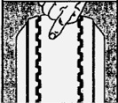
Wheel Bearing Lubrication
There is no need to lift the vehicle before greasing axles equipped with today’s modern “easy-lube” technologies:
Remove the rubber plug from grease cap.
Insert grease gun on the grease zerk.
Pump until new grease begins to appear.
Replace rubber plug.
Hubs and components should also be disassembled yearly and inspected for worn or otherwise damaged parts.
|
|
|
keep tires properly inflated. a tire that is run long distances or at high speeds while seriously underinflated will overheat to the point where the tire may lose air suddenly and/or catch fire, possibly resulting in damage to the vehicle and its contents and or personal injury. |
Tires and Wheels
The tires should be checked before starting on every trip. Check them regularly and keep inflated to recommended pressures. The recommended tire pressure is on the side of the tire. Rotate tires at least once every 5,000 miles or as recommended by the tire manufacturer. Most models have a spare tire available in case of an emergency.
All vehicles are equipped with tubeless tires. They are designed for today’s turnpike speeds and are rated to carry the weight of the trailer plus your family’s personal needs for an extended vacation. If you should require an adjustment on a faulty or defective tire, secure the name of your nearest tire dealer or distributor and request an adjustment according to the conditions and terms of the warranty.
Tire Changing
- Use emergency flares when near a road or highway.
- Block wheels on the opposite side from the tire you wish to change to prevent accidental movement.
- Position a hydraulic jack on the frame close to the spring hanger.
- Raise the trailer until the tire clears the ground.
|
|
|
Check tire pressures before traveling. Always check tire pressure when tires are cold. Do not exceed the maximum recommended pressure. |
The Importance of Proper Tire Inflation
Your trailer tires and wheels, and tongue or fifth-wheel hitch, support the entire weight of the trailer and its contents. The tires are also the only contact the trailer has with the road surface. Determining and maintaining proper inflation is the most important factor in maximizing the life of your tires. Driving on a tire that does not have the correct inflation pressure for the trailer load is dangerous and may cause premature wear, tire damage, tread delaminating and/or loss of control of the trailer and/or tow vehicle.
An under-inflated tire will build up excessive heat that may go beyond the limits of the tire materials. This could result in sudden tire failure. An under-inflated tire will also cause poor vehicle handling, rapid and/or irregular tire wear, and an increase in rolling resistance which results in decreased tow vehicle fuel economy.
The maximum cold inflation pressure for your tires is stated on the tire sidewalls. Keep your tires inflated to the maximum cold pressure. This reduces the chance of a failure and improves towing stability. Maintaining correct tire inflation pressure for your trailer is of the utmost importance and must be a part of regular vehicle maintenance.
You must weigh your trailer when it is fully loaded as you expect to use it. You need to weigh all axles together and calculate the hitch weight. You may find that even thought the total weight is within the GVWR, one side may be overloaded. For this reason, you must know the weight of each side of the trailer. When you know the weight on each side of the trailer, the combined axle assembly, and the hitch weight, you will be able to manage your loading to be able to maintain good balance and assure good and safe handling on the road. Here are some tips to help you plan your loading:
- Do not overload. Experiment with various loads starting with light loads and working up to heavier loads. Take into consideration the load of the fresh water system. The tow vehicle and the terrain will affect the true weight you should carry.
- Distribute the load evenly over the axles as much as possible. Keep heavy items low and forward, preferably in the lower storage areas. This will produce a lower center of gravity, and improve road stability.
- Distribute the load evenly on each side of the trailer. Place heavier object opposite the heavier appliances, cabinets, furniture, etc. when possible. Experiment with various load positions until you find the best distribution.
- Avoid loading heavy items in or on the rear of the trailer. This can cause both total weight problems and hitch weight distribution problems.
- Secure items so they won’t move around while traveling. Make sure all items and materials are properly stored. Close and latch all drawers, cabinet doors, and closet doors. Pull all loose furniture away from cabinets and walls, and lie on their side or secure to prevent rubbing during travel.
- Carry only as much water as you think you will need while traveling. Water weighs over eight pounds per gallon. Whenever possible, empty the holding tanks before going on the road.
- If you are heading for rough terrain, use heavy packing material in the cupboards to hold plates, glasses, etc. Put a nonskid material beneath heavier items to prevent shifting. Expensive and breakable belongings should be well packed and placed on the floor in the center of the trailer, as the center rides best.
- Store emergency items, such as fire extinguisher, first-aid kit, highway warning devices, gloves, etc. in a readily accessible place. Do not bury these items beneath other cargo.
- When you have properly loaded your trailer with the things you need for your trip, make a diagram that outlines where things are stored. With this diagram, your list of items and the weight of the items, you will be able to find specific items easily and have a hand reference for determining proper weights.
- Weigh your trailer after you have loaded it. You have to do this several times to get it right.
|
|
|
Tire load ratings are dependent on tire inflation pressures. Under-inflated tires can be damaged and result in a loss of inflation pressure. |
Check the trailer tires frequently. Tires can lose air over a period of time. In fact, tires can lose 1 to 3 PSI per month. This is because molecules of air, under pressure, migrate through the rubber from the inside to the outside. A drop in tire pressure could cause the tired to become overloaded, leading to excessive heat buildup. If a trailer tire is under-inflated, even for a short period of time, the tire could suffer internal damage. A flat can go unnoticed on a multiple axle trailer while it is being towed. Running with a flat can cause it to catch fire and burn up your rig. With multiple axles or tandem wheels it is hard sometimes to see a flat tire as the other tires are supporting the weight of the rig and the flat tire is less noticeable. A quick check can be made by “thumping” each tire with a tire iron or rod to make sure they all sound the same. Each time you gas up, walk around the trailer and give a quick check by feeling each tire with your hand. A tire that is getting low will be hotter than the rest. There is no substitute, however, for actually measuring tire pressures to make sure they are all within safe limits. Always check the cold tire inflation pressures before each trip and at least once a week during the trip for proper inflation levels.
The most common causes of tire failure are overloading and underinflation. Both result in excess flexing of the tire sidewall which causes heat buildup and eventual tire failure. Continuing to run with a flat can cause it to catch fire.
The most important things you can do to avoid tire fires are:
- Maintain proper tire pressure
- Stay within tire and vehicle road limits
- Avoid road hazards if possible
- Inspect tires for cuts, slashes, and other irregularities.
Properly maintained tires improve the steering, stopping, traction, and load-carrying capability of your vehicle. Make tire safety a regular part of your vehicle maintenance routine. Recognize that the time you spend is minimal compared with the inconvenience and safety consequences of a flat tire or other tire failure.
Understanding Tire Pressure and Load Limits
Tire inflation pressure is the level of air in the tire that provides it with load-carrying capacity and affects the overall performance of the vehicle. The tire inflation pressure is a number that indicates the amount of air pressure a tire requires to be properly inflated. It is difficult to obtain the recommended tire pressure if your tires are not cold. Because tires are designed to be used on more than one type of vehicle, tire manufacturers list the “maximum permissible inflation pressure” on the tire sidewall. This number is the greatest amount of air pressure that should ever be put in the tire under normal driving conditions.
|
|
The air pressure recommended on the tire information placard is for the original standard equipment tires only. Your trailer may be equipped with optional-sized tires. Always follow the pressure recommendations stamped on the tire sidewall for any replacement tire. |
Checking and Adjusting Tire Pressure
It is important to check your vehicle’s tire pressure at least once a month, always before each trip, and at least once a week while on the road. Not only do tires naturally lose pressure over time, but they can lose air suddenly if you drive over a pothole or other object, or if you strike the curb. It is difficult to determine tire inflation pressure by looking at the tire. Purchase a tire pressure gauge to keep in your vehicle. Gauges can be purchased at tire dealerships, auto supply stores and other retail outlets.
The recommended tire inflation pressure that vehicle manufacturers provide reflects the proper psi when a tire is cold. A “cold” tire is one that has not been driven on for at least three hours. When you drive, your tires get warmer, causing the air pressure within them to increase. Therefore, to get an accurate tire pressure reading, you must measure tire pressure when the tires are cold.
Refer to the tire’s sidewalls for the recommended tire pressure. Your trailer may be equipped with optional tires.
Check and write down the pressure in all tires.
If the tire pressure is too high in any of the tires, slowly release air by gently pressing on the tire valve stem with the edge of your tire gauge until you get to the correct pressure.
If the tire pressure is too low, note the difference between the measured tire pressure and the correct tire pressure. You will need to add air to get to the correct pressure.
Add air pressure to each tire that is under-inflated.
Check all the tires again to make sure they have the same air pressure.
If you have been towing your trailer and think that a tire is under-inflated, fill it to the recommended cold inflation pressure. Remember to recheck and adjust the pressure in all tires when you can obtain a cold reading.
Tire Tread
The tire tread provides the gripping action and traction that prevent your vehicle from slipping or sliding, especially when the road is wet or icy. In general, tires are not safe and should be replaced when the tread is worn down to 1/16 of an inch. Tires have built-in tread-wear indicators that let you know when it is time to replace your tires. These indicators are raised sections spaced intermittently in the bottom of the tread grooves. When they appear “even” with the outside of the tread, it is time to replace your tires.
Tire Life
Trailer tires may be worn out even though they still have plenty of tread left. This is because trailer tires have to carry a lot of weight all the time, even when not in use. It is actually better for a tire to be rolling down the road than to be idle. During use, the tire releases lubricants that are beneficial to tire life. Using the trailer tires often also helps prevent flat spots from developing. The average life of a trailer tire is about five years under normal use and maintenance conditions. After five years, trailer tires may be degraded to the point that they should be replaced, even if they have had minimal or no use. Exposure to sunlight (ultra-violet damage) and high speed towing in hot conditions also reduces tire life. As heat builds up during driving, the tire’s internal structure starts to break down, compromising the strength of the tire. Have your tires inspected by a tire supplier to determine if your tires need to replaced.
|
|
|
All tires on your trailer should be the same type, size, construction and lead rating – do not mix bias-belted and radial tires. |
Replacement Tires
To maintain tire safety, purchase new tires that are the same type, size, construction and load ratings as the original tires. Look at the tire Information placard, or the sidewall of the tire you are replacing to find this information. If you have any doubt about the correct size to choose, consult with the tire dealer.
|
|
|
There is a danger of serious injury or death if a tire of one bead diameter is installed on a rim or wheel of a different rim diameter. ALWAYS replace a tire with another tire of exactly the same bead diameter designation and suffix letters. |
Tire Safety Information
This portion of the Owner’s Manual contains tire safety information as required by 49 CFR 575.6
The National Highway Traffic Safety Administration (NHTSA) has published a brochure (DOT HS 809 36) that discusses all aspects of Tire Safety, as required by CFR 575.6. It can be obtained and downloaded from NHTSA, free of charge, from the following web site:
http://www.NHTSA.dot.gov/cars/rules/TireSafety/ridesonit/tires_index.html
Studies of tire safety show that maintaining proper tire pressure, observing tire and vehicle load limits (not carrying more weight in your vehicle than your tires or vehicle can safely handle), avoiding road hazards, and inspecting tires for cuts, slashes, and other irregularities are the most important things you can do to avoid tire failure, such as tread separation or blowout and flat tires.
These actions, along with other care and maintenance activities, can also:
- Improve vehicle handling
- Help protect you and others from avoidable breakdowns and accidents
- Improve fuel economy
- Increase the life of your tires.
Use this information to make tire safety a regular part of your vehicle maintenance routine. Recognize that the time you spend is minimal compared with the inconvenience and safety consequences of a flat tire or other tire failure.
Safety First – Basic Tire Maintenance
Properly maintained tires improve the steering, stopping, traction, and load-carrying capability of your vehicle. Under-inflated tires and overloaded vehicles are a major cause of tire failure. Therefore, as mentioned above, to avoid flat tires and other types of tire failure, you should maintain proper tire pressure, observe tire and vehicle load limits, avoid road hazards, and regularly inspect your tires.
Finding Your Vehicle’s Recommended Tire Pressure and Load Limits
Tire information placards and vehicle certification labels contain information on tires and load limits. These labels indicate the vehicle manufacturer’s information including:
- Recommended tire size
- Recommended tire inflation pressure
- Vehicle capacity weight (VCW–the maximum occupant and cargo weight a vehicle is designed to carry)
- Front and rear gross axle weight ratings (GAWR– the maximum weight the axle systems are designed to carry).
Both placards and certification labels are permanently attached to the trailer on the forward half of the left side, and are easily readable from outside the vehicle without moving any part of the vehicle.
Tire Repair
The proper repair of a punctured tire requires a plug for the hole and a patch for the area inside the tire that surrounds the puncture hole. Punctures through the tread can be repaired if they are not too large, but punctures to the sidewall should not be repaired. Tires must be removed from the rim to be properly inspected before being plugged and patched.
Tire Fundamentals
Federal law requires tire manufacturers to place standardized information on the sidewall of all tires. This information identifies and describes the fundamental characteristics of the tire and also provides a tire identification number for safety standard certification and in case of recall.
Tire Label Information
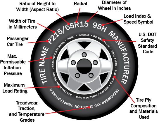
|
notice |
|
Your trailer is equipped with tires designated as “ST”. This designation means that the tires are built specifically for trailer applications. They are correct for your trailer and the maximum loads the trailer was designed and rated to carry. Tire industry standards require that tires with “ST” designation are speed restricted to 65 MPH under normal inflation and load conditions. Unless a different speed restriction is indicated on the sidewall of the tire, it is best that you do not operate your trailer at speeds above 65 MPH. |
P - The “P” indicates the tire is for passenger vehicles.
NOTE: Passenger car tires are not recommended for use on trailers.
LT - The “LT” indicates the tire is for light trucks or trailers.
|
notice |
|
Although tires designated “LT” are sometimes used on trailers, they are not recommended for use on your trailer and should not be considered as replacements for the original equipment “ST” designated tires. |
ST - An “ST” is an indication the tire is for trailer use only
Next number - This three-digit number gives the width in millimeters of the tire from sidewall edge to sidewall edge. In general, the larger the number, the wider the tire.
Next number - This two-digit number, known as the aspect ratio, gives the tire’s ratio of height to width.
R - The “R” stands for radial. Other tire designs may be “bias ply” or “bias belted” and are designated by other letters.
Next number - This two-digit number is the wheel or rim diameter in inches. If you change your wheel size, you will have to purchase new tires to match the new wheel diameter.
Next number - This two- or three-digit number is the tire’s load index. It is a measurement of how much weight each tire can support. You may find this information in your owner’s manual. If not, contact a local tire dealer.
Note: You may not find this information on all tires because it is not required by law.
Speed Rating - The speed rating denotes the speed at which a passenger car tire is rated. A speed rating will not be found on “ST” tires used on trailers. All “ST” tires are speed restricted to 65 mph. Never operate a vehicle in an unsafe or unlawful manner. Tire speed ratings (if indicated) should never be associated with the ability of the vehicle to handle the speed for which the tire is rated.
U.S. DOT Tire Identification Number
This begins with the letters “DOT” and indicates that the tire meets all federal standards. The next two numbers or letters are the plant code where it was manufactured, and the last four numbers represent the week and year the tire was built. For example, the numbers 3197 means the 31st week of 1997. The other numbers are marketing codes used at the manufacturer’s discretion. This information is used to contact consumers if a tire defect requires a recall.
Tire Ply Composition and Materials Used
The number of plies indicates the number of layers of rubber-coated fabric in the tire. In general, the greater the number of plies, the more weight a tire can support. Tire manufacturers also must indicate the materials in the tire, which include steel, nylon, polyester, and others.
Maximum Load Rating
This number indicates the maximum load in kilograms and pounds that can be carried by the tire.
Maximum Permissible Inflation Pressure
This number is the greatest amount of air pressure that should ever be put in the tire under normal driving conditions.
Vehicle Load Limits
Determining the load limits of a vehicle includes more than understanding the load limits of the tires alone. A Federal Certification Label is located on the forward half of the left (road) side of the unit. The certification label will indicate the vehicle’s gross vehicle weight rating (GVWR). This is the most the fully loaded vehicle can weigh. It also provides the gross axle weight rating (GAWR). This is the maximum weight a particular axle can carry. If there are multiple axles, the GAWR of each axle will be provided. In the same location as the certification label described above, there is a vehicle placard. This placard provides tire and loading information. In addition, this placard will show a statement regarding maximum cargo capacity.
Cargo Capacities
Cargo can be added to the vehicle, up to the maximum weight specified on the placard. The combined weight of the trailer and cargo is provided as a single number. In any case, remember: The total weight of a fully loaded vehicle can not exceed the stated GVWR.
Water and propane also need to be considered. The weight of fully filled propane containers is considered part of the weight of the RV before it is loaded with cargo and is not considered part of the disposable cargo load. Water however, is a cargo weight and is treated as such. If there is a fresh water storage tank of 100 gallons, this tank when filled would weigh about 800 pounds. If more cargo is being transported, water can be off-loaded to keep the total amount of cargo added to the vehicle within the limits of the GVWR so as not to overload the vehicle.
Understanding this flexibility will allow you, the owner, to make choices that fit your travel and camping needs.
When loading your cargo, be sure it is distributed evenly to prevent overloading front to back and side to side. Heavy items should be placed low and as close to the axle positions as reasonable. Too many items on one side may overload a tire. The best way to know the actual weight of the vehicle is to weigh it at a public scale. Talk to your RV dealer to discuss the weighing methods needed to capture the various weights related to the RV. This would include weights for the following: axles, wheels, hitch or pin (in the case of a trailer) and total weight.
How Overloading Affects Your RV and Tires
The results of overloading can have serious consequences for passenger safety. Too much weight on your vehicle’s suspension system can cause spring, shock absorber, or brake failure, handling or steering problems, irregular tire wear, tire failure or other damage. An overloaded vehicle is hard to drive and hard to stop. In cases of serious overloading, brakes can fail completely, particularly on steep hills. The load a tire will carry safely is a combination of the size of tire, its load range, and corresponding inflation pressure. Excessive loads and/or under-inflation cause tire overloading and, as a result, abnormal tire flexing occurs. This situation can generate an excessive amount of heat within the tire. Excessive heat may lead to tire failure. It is the air pressure that enables a tire to support the load, so proper inflation is critical. Since RVs can be configured and loaded in many ways, air pressures must be determined from actual loads (determined by weighing) and taken from the load and inflation tables provided by the tire manufacturer. These air pressures may differ from those found on the certification label. However, they should never exceed the tire limitation for load or air pressure. If you discover that your tires cannot support the actual weights, the load will need to be lightened.
Tire Safety Tips
Preventing Tire Damage
- Slow down if you have to go over a pothole or other object in the road.
- Do not run over curbs or other foreign objects in the roadway, and try not to strike the curb when parking.
Tire Safety Checklist
- Check tire pressure (including the spare) at least once a month and before going on any trip.
- Inspect tires for uneven wear patterns on the tread, cracks, foreign objects, or other signs of wear or trauma.
- Remove bits of glass and foreign objects wedged in the tread.
- Make sure your tire valves have valve caps.
- Do not overload your vehicle. Check the Tire Information and Loading Placard or User’s Manual for the maximum recommended load for the vehicle.
Steps for determining correct load limit
- Locate the statement “The weight of cargo should never exceed XXX KG or XXX LBS” on your vehicles placard.
- The figure stated on the placard is the available amount of cargo load capacity
- Determine the weight of cargo being loaded in the vehicle. That weight may not safely exceed the available cargo capacity.
For further information about wheel and tire safety:
1-888-327-4236 (TTY: 1-800-242-9 53)
http://www.safercar.gov
and NHTSA
400 Seventh St. S.W.
Washington, DC 20590
Storage of Tires
Rubber tires degrade faster when not being used. A cool, dry, sealed garage is the preferred storage location. Many recreational vehicles are stored outside. Some storage surfaces may cause tires to prematurely age. Placing a barrier (plastic or plywood) between the tire and storage floor/ground helps to protect the tires. When the tire may be out of service for 30 days or more, the vehicle should be in long-term storage condition.
|
|
IF THE RECREATIONAL VEHICLE IS STORED WITH WEIGHT ON THE TIRES, INFLATE THEM TO MAXIMUM INFLATION PRESSURE AS INDICATED ON THE FEDERAL IDENTIFICATION TAG. |
- Thoroughly clean the tires.
- Unload the vehicle so there is minimum weight on the tires.
- Ensure the surface is reasonably level, firm, clean and has good drainage.
- Move recreational vehicle every three months to prevent cracking in bulge areas as well as flat spotting from prolonged sidewall strain and tread deflection.
- Cover the tires to block direct sunlight and ultraviolet rays.
- The parking surface will affect moisture accumulation on the chassis and flooring.
- Gravel covered parking areas allow moisture to evaporate into the underside of the recreational vehicle.
- Sealed concrete pads allow better ventilation under the recreational vehicle.
- Storage buildings with sealed concrete floors or heated facilities greatly reduce the amount of moisture accumulation and protect the recreational vehicle from moisture damage.
- Avoid wet or greasy surfaces. Avoid highly reflective surfaces like asphalt, sand or snow.
Before removing the vehicle from long-term storage, thoroughly inspect each tire tread area and air pressure. If the pressure check indicates tires have lost air, inflate to correct pressure for current load before use.
Support Tires When Leveling
Extreme caution must be taken to ensure the tires are fully supported when placing blocks under the tires. The load on the tire should be evenly distributed on the support block. In case of dual tires, distribute the load evenly on blocks for both tires. If not properly supported, the steel cables in the sidewall of the tires may be damaged and could lead to premature fatigue of the sidewall.
|
|
|
SUPPORTING TIRES PREVENTS DAMAGE TO THE SIDEWALL OF THE TIRES, BUT DOES NOT PREVENT TIRE ROLL. |
In Case of Flat Tire
In the event of a flat tire, it is recommended to call for roadside assistance. The size and weight of the trailer requires the proper equipment to change the tire. A professional service technician will have the equipment and training necessary to repair or replace the tire. In the event of sudden tire failure, avoid heavy braking. Slowly move to a safe, off-road location, which should be a firm, level area. Turn the hazard flasher system on. Inform roadside assistant of proper wheel mounting procedures.
|
|
|
IN CASE THE TRAILER REQUIRES TOWING, ENSURE ALL PRECAUTIONS ARE FOLLOWED. THE MANUFACTURER WILL NOT COVER DAMAGE TO THE TRAILER CAUSED BY A TOWING COMPANY. NEVER ALLOW ANYONE TO GO UNDER A TRAILER WHILE IT IS BEING LIFTED BY TOWING EQUIPMENT. SERIOUS INJURY OR LOSS OF LIFE COULD RESULT. |
Electric Brake System
The electric brakes on your vehicle are similar to those in your automobile; the difference being that they are activated by 12 volt electrical impulse as opposed to a hydraulic system. The impulse comes from a brake controller, which in effect regulates the flow of electrical current to the trailer brakes.
Brakes are usually maintenance free; however, road and driving conditions may at times cause them to grab, drag, or fade. Also, improper grounding of the trailer to the tow vehicle, irregular current, or a short circuit in the wiring system will cause electric brakes to malfunction. In any case, we strongly recommend that you consult your dealer or local trailer brake specialist on these problems.
|
|
|
IF ANY KIND OR DEGREE OF BRAKE FAILURE OCCURS, HAVE THE BRAKES REPAIRED IMMEDIATELY. CONTINUED DRIVING IS DANGEROUS AND COULD RESULT IN SERIOUS INJURY OR LOSS OF LIFE. |
Electric brakes should be checked prior to every trip to determine the condition of the magnets and drums, and whether wiring connections are still secure (see manufacturer’s instructions). Brakes can be adjusted to activate ahead of the tow vehicle brakes for best road control. Consult the manufacturer’s instructions or you dealer for detailed information and service procedures.
Synchronization of Brakes
Recreational vehicle brakes are designed to work in synchronization with tow vehicle brakes. Never use tow vehicle or recreational vehicle brakes alone to stop the combined load. The recreational vehicle and tow vehicle will seldom have correct amperage flow to the brake magnets to give comfortable, safe braking unless proper brake system adjustments are made. Changing the recreational vehicle load and driving conditions, as well as uneven alternator and battery output, can mean unstable current flow to brake magnets. It is imperative to maintain and adjust brakes as set forth in this manual, use properly modulated brake controller and perform the synchronization procedure noted below.
In addition to the synchronization adjustments, electric brake controllers provide a modulation function that varies the current to the electric brakes with the pressure on the brake pedal or amount of deceleration of the tow vehicle. It is important that the brake control provide about 2 Volts to the braking system when the brake pedal is first depressed and gradually increases the voltage to 12 Volts as brake pedal pressure is increased. If the controller “jumps” immediately to high voltage output, even during a gradual stop, the electric brakes will always be fully energized and will result in harsh brakes and potential wheel lock-up.
Proper synchronization of tow vehicle to recreational vehicle braking can only be accomplished by road testing.
Brake lock-up, grabbing or harshness is often due to the lack of synchronization between the tow vehicle and the recreational vehicle being towed, too high of a threshold voltage (over 2 Volts), or under adjusted brakes.
Before synchronization adjustments are made, the recreational vehicle brakes should be burnished in by applying the brakes 2 or 3 times with about a 20 mph decrease in speed, e.g. 40 mph to 20 mph – Allow ample time for brakes to cool between applications, letting brake shoes and magnets to slightly wear-in to drum surfaces.
Controllers
To ensure safe brake performance and synchronization, completely read the brake controller manufacturer’s instructions before attempted synchronization procedure. Make several hard stops from 20 mph on a dry paved road, free of sand and gravel. If the recreational vehicle brakes lock immediately, decrease gain setting on the controller. If they do not approach progressive lock-up slightly increase the gain setting.
|
|
|
ROAD TEST BEFORE USING. BE SURE AREA IS CLEAR OF TRAFFIC AND PEDESTRIANS. DO NOT EXCEED 30 M.P.H. FOLLOW PROCEDURES OUTLINED BY THE CONTROLLER MANUFACTURER. FAILURE TO DO SO COULD RESULT IN PROPERTY DAMAGE, SERIOUS PERSONAL INJURY, OR LOSS OF LIFE. |
|
|
MINIMUM VEHICLE STOPPING DISTANCES ARE ACHIEVED WHEN WHEELS APPROACH LOCK-UP. AVOID BRAKE LOCK-UP AS IT RESULTS IN POOR VEHICLE STABILITY AND CONTROL. DEPENDING ON THE LOAD, BRAKE TYPE, WHEELS AND TIRES, NOT ALL RECREATIONAL VEHICLE BRAKES ARE CAPABLE OF WHEEL LOCK-UP. |
If the controller is applying recreational vehicle brakes before the tow vehicle brakes, adjust controller level so the recreational vehicle brakes comes on in synchronization with the tow vehicle brakes. Adjust controller to allow recreational vehicle brakes to come on just slightly ahead of the tow vehicle brakes. When proper synchronization in achieved there will be no sensation of the recreational vehicle jerking or “pushing” the tow vehicle during braking.
Start by making sure the recreational vehicle brakes are properly adjusted. Some controllers have a gain control to vary the amount of current to the brakes and a level control which sets the controller inertia sensor to sense deceleration. The level adjustment can also vary when the recreational vehicle braking is felt. Gain, or output control, adjustment usually controls maximum amount of amperage available to the brakes. This can be adjusted for varying recreational vehicle load.
|
|
|
DO NOT ADJUST THIS CONTROL OUTSIDE THE PARAMETERS OUTLINED BY THE BRAKE CONTROLER MANUFACTURER’S INSTRUCTIONS. |
Brake Adjustment
Brakes should be adjusted by a service dealer after the first 200 miles of operation when the brake shoes and drums have seated, at 3,000 mile intervals, or as use performance requires. The electric brakes are of the drum and two shoe type and adjust the same as most automotive drum brakes. The adjusting screw is accessible through a hole at the bottom of the backing plate. Remove the hole plug and use a standard brake adjusting tool. Turn the screw until the shoes contact the drum and with enough force to make the wheel hard to turn by hand. Then back off the screw ¾ to one full turn or until the wheel turns freely.
Brake Cleaning and Inspection
The recreational vehicle brakes must be inspected and serviced yearly, or more often. Magnets and shoes must be changed when they become worn or scored. Wear or scoring may inhibit vehicle braking. Clean the backing plate, magnet arm, magnet and brake shoes. Make sure that all the parts are removed and replaced in the same brake and drum assembly. Inspect the magnet arm for any loose or worn parts. Check shoe return springs. Hold down the springs and the adjuster springs to check for stretch or deformation. Replace if necessary.
|
|
|
SOME BRAKE SHOE FRICTION MATERIALS CONTAIN ASBESTOS. CERTAIN PRECAUTIONS MUST BE TAKEN WHEN SERVICING BRAKES: AVOID CREATING OR BREATHING DUST; AVOID MACHINING, FILING OR GRINDING THE BRAKE LINING; DO NOT USE COMPRESSED AIR OR DRY BRUSHING FOR CLEANING. (DUST CAN BE REMOVED WITH A DAMP BRUSH.) |
Maintain Safe Braking Distance
Braking action involves perception time and reaction time. First a person has to decide to push on the brake pedal. That is perception time. Then that person has to bring up their foot to do it. That is reaction time.
Average reaction time is about ¾ of a second. But that is only an average. It will be less with one driver and more (up to two or three seconds) with another. Age, physical condition, alertness, coordination and eyesight all will play a part in the perception time and reaction time. So do alcohol, drugs and frustration.
But even in ¾ of a second, a vehicle, such as a truck, moving at 60 mph (100 km/h) travels 66 feet (20 m). That is without a trailer behind it. That could be a lot of distance in an emergency, so keeping enough space between your vehicle and others is very important. Especially when considering that it takes ever longer to stop when you have a heavy trailer attached to your tow vehicle.
Of course, actual stopping distances vary greatly with the surface of the road (whether it is gravel or pavement); the condition of the road (wet, dry, icy); tire tread; the condition of your brakes; the weight of the vehicle and the amount of brake force applied.
The distance required to properly stop when towing a vehicle is often underestimated. As a good rule of thumb, when towing the trailer, always maintain at least 3 cars and a trailer (approximately 85 ft) length space between you and the car in front of you for every 10 miles of speed you are traveling. This should give you ample time to stop in case of an emergency.
BREAKAWAY SWITCH
Breakaway switches provide a means of automatically stopping your RV if it should become detached from your tow vehicle during transit. The cable from the break-away switch should be attached to the tow vehicle in a manner of which it will remain connected even if the hitch becomes uncoupled.
The break-away switch gets its power from an auxiliary 12-volt battery. This battery may not be provided with your unit and may need to be obtained prior to moving (see your dealer). If the RV should become disconnected from the tow vehicle, the pin is pulled out of the switch and current from the RV battery is applied to the trailer brakes. Occasionally, pull the pin from the switch to test for proper operation.
|
|
|
Always make sure the pin is returned completely or the brakes will continue to draw power from the battery, thus discharging the battery. Check for proper battery charge prior to any trip. |
Tire Changing Basics
|
|
|
The optional spare tire is intended for short term emergency use only. |
Position a hydraulic jack on the frame close to the spring hanger. (Never attempt to use a stabilizer jack to lift the unit.)
- Block the wheels on the opposite side from the tire you wish to change to prevent accidental movement.
- Use emergency flares when near a road or highway.
- Place hydraulic jack on a level surface under the frame rail as close to the jack as possible.
- Loosen the lug nuts.
- Raise the trailer until the tire clears the ground
- Remove the lug nuts and remove the tire.
- Install the spare tire and install the lug nuts until the wheel is tight against the hub.
- Lower the trailer
- Torque the lug nuts following the Wheel Nut Torque Procedure in this manual.
- Recheck the torque every 50 miles for the first 200 miles.
|
|
Use a torque wrench to tighten lug nuts. Tightening by hand or with an impact wrench is not recommended. Torque to: 120 Ft. Lbs |
Accessory Weight – The combined weight (in excess of those standard items which may be replaced) of automatic transmission, power steering, power brakes, power windows, power seats, radio and heater, to the extent that these items are available as factory-installed equipment (whether installed or not).
Bead – The part of the tire that is made of steel wires, wrapped or reinforced by ply cords and that is shaped to fit the rim.
Bead Separation – This is the breakdown of the bond between components in the bead.
Bias Ply Tire – A pneumatic tire in which the ply cords that extend to the beads are laid at alternate angles substantially less than 90 degrees to the centerline of the tread.
Carcass – The tire structure, except treat and sidewall rubber which, when inflated, bears the load.
Chunking – The breaking away of pieces of the tread or sidewall.
Cold Inflation Pressure – The pressure in the tire before you drive.
Cord – The strands forming the plies in the tire.
Cord Separation – The parting of the cords from adjacent rubber compounds.
Cracking – Any parting within the tread, sidewall, or inner liner of the tire extending to cord material.
CT – A pneumatic tire with an inverted flange tire and rim system in which the rim is designed with rim flanges pointed radially inward and the tire is designed to fit on the underside of the rim in a manner that encloses the rim flanges inside the air cavity of the tire.
Curb Weight – The weight of a motor vehicle with standard equipment including the maximum capacity of fuel, oil, and coolant, and, if so equipped, air conditioning and additional weigh optional engine.
Extra Load Tire - A tire designed to operate at higher loads and at higher inflation pressures than the corresponding standard tire.
Groove – The space between two adjacent tread ribs.
Gross Vehicle Weight Rating (GVWR) – The maximum permissible weight of this fully loaded RV.
Gross Axle Weight Rating (GAWR) – The value specified as the load carrying capacity of a single axle system, as measure at the tire-ground interfaces.
Hitch Weight – The vertical trailer load supported by the hitch ball.
Innerliner – The layer(s) forming the inside surface of a tubeless tire that contains the inflating medium within the tire.
Innerliner Deparation – The parting of the inner line from cord material in the carcass.
Intended Outboard Sidewall – The sidewall that contains a whitewall, bears white lettering or bears manufacturer, brand, and/or model name molding that is higher or deeper than the same molding on the other sidewall of the tire or the outward facing sidewall of an asymmetrical tire than has a particular side that must always face outward when mounted on a vehicle.
Light Truck (LT) Tire – A tire designated by its manufacturer as primarily intended for use on lightweight trucks or multipurpose passenger vehicles.
Load Rating – The maximum load that a tire is rated to carry for a given inflation pressure.
Maximum Permissible Inflation Pressure – The maximum cold inflation pressure to which a tire may be inflated.
Maximum Loaded Vehicle Weight – The sum of curb weight, accessory weight, vehicle capacity weight, and production options weight.
Measuring Rim – The rim on which a tire is fitted for physical dimension requirements.
Non-Pneumatic Rim – A mechanical device which, when a non-pneumatic tire assembly incorporates a wheel, supports the tire, and attaches, either integrally or separably, to the wheel center member and upon which the tire is attached.
Non-Pneumatic Spare Tire Assembly – A non-pneumatic tire assembly intended for temporary use in place of one of the pneumatic tires and rims that are fitted to a passenger car in compliance with the requirements of this standard.
Non-Pneumatic Tire – A mechanical device which transmits, either directly or through a wheel or wheel center member, the vertical load and tractive forces from the roadway to the vehicle, generates the tractive forces that provide the directional control of the vehicle and does not rely on the containment of any gas or fluid for providing those functions.
Non-pneumatic Tire Assembly – A non-pneumatic tire, alone or in combination with a wheel or wheel center member, which can be mounted on a vehicle.
Open Splice – Any parting at any junction of tread, sidewall, or innerliner that extends to cord material.
Outer Diameter – The overall diameter of an inflated new tire.
Overall Width – The linear distance between the exteriors of the sidewalls on an inflated tire, including elevations due to labeling, decorations, or protective bands or ribs.
Pin Weight – The vertical trailer load supported by the king pin of a fifth-wheel hitch.
Ply – A layer of rubber-coated parallel cords.
Ply Separation – A parting of rubber compound between adjacent plies.
Pneumatic Tire – A mechanical device made of rubber, chemicals, fabric and steel or other materials, that, when mounted on an automotive wheel, provides the traction and contains the gas or fluid that sustains the load.
Production Options Weight – The combined weight of those installed regular production options weighing over 23 kilograms (5lbs.) in excess of those standard items which they replace, not previously considered in curb weight or accessory weight, including heavy duty brakes, ride levelers, roof rack, heavy duty battery, and special trim.
Radial Ply Tire – A pneumatic tire in which the ply cords that extend to the beads are laid at substantially 90 degrees to the centerline of the tread.
Recommended Inflation Pressure – This is the inflation pressure provided by the vehicle manufacturer on the Tire Information label and on the Certification/VIN tag.
Reinforced Tire – A tire designed to operate at higher loads and at higher inflation pressures than the corresponding standard tire.
Rim – A metal support for a tire or a tire and tube assembly upon which the tire bears are seated.
Rim Diameter – This means the nominal diameter of the beat seat.
Rim Size Designation - This means the rim diameter and width.
Rim Type Designation – This means the industry of manufacturer’s designation for a rim by style or code.
Rim width – This means the nominal distance between rim flanges.
Section Width – The linear distance between the exteriors of the sidewalls of an inflated tire, excluding elevations due to labeling, decoration, or protective bands.
Sidewall – The portion of a tire between the tread and bead.
Sidewall Separation – The parting of the rubber compound from the core material in the sidewall.
Test Rim – The rim on which a tire is fitted for testing, and may be any rim listed as appropriate for use with that tire.
Tread – That portion of a tire that comes into contact with the road.
Tread Rib – A tread section running circumferentially around a tire.
Tread Separation – Pulling away of the tread from the tire carcass.
Treadwear Indicators (TWI) – The projections within the principal grooves designed to give a visual indication of the degree of wear of the tread.
Vehicle Capacity Weight – The rated cargo and luggage load plus 68 kilograms (150 lbs.) times the vehicle’s designated seating capacity.
Vehicle Maximum Load On The Tire – The load on an individual tire that is determined by distributing to each axle its share of the maximum loaded vehicle weight and dividing by two.
Vehicle Normal Load On The Tire – The load on an individual tire that is determined by distributing to each axle its share of the curb weight, accessory weight, and normal occupant weight (distributed in accordance with Table I of CRF 49571.110) and dividing by 2.
Weather Side – The surface area of the rim not covered by the inflated tire.
Wheel Center Member – In the case of a non-pneumatic tire assembly incorporating a wheel, a mechanical device which attaches, either integrally or separably, to the non-pneumatic rim and provides the connection between the non-pneumatic rim and the vehicle; or, in the case of a non-pneumatic tire assembly not incorporating a wheel, a mechanical device which attaches, either integrally or separably, to the non-pneumatic tire and provides the connection between tires and the vehicle.
Wheel-holding Fixture – The fixture used to hold the wheel and tire assembly securely during testing.
Set Up Procedures
This section outlines the procedures necessary to stabilize and set up your vehicle. Before attempting to set up the vehicle, carefully read and understand these instructions. Setting up your vehicle requires forethought and care.
Your vehicle is designed to be efficient and comfortable. Careful attention to detail and thoroughness during set up will ensure that you will benefit from all the features and comfort built into your vehicle.
During storage or after your vehicle has been set up, you may notice a slight rippling or waviness of the fiberglass exterior sidewall panels if your vehicle is sitting in the sun. This is caused by the normal expansion of the materials as they warm up. As the temperature goes down these panels will tend to return to their original shape. This condition is typical and is not covered under the Breckenridge warranty.
Leveling and Stabilization
Leveling of your trailer at the site is essential. A level trailer is not only necessary for comfort but your refrigerator must be level in order to operate properly. Stabilization is recommended to keep the vehicle from bouncing while unhitched when people are moving inside the vehicle.
Stabilizer jacks are intended to stabilize the vehicle body while the vehicle’s full weight is supported by the hitch jack (conventional vehicles) and running gear. Stabilizer jacks are not designed to lift or support its entire weight. If your coach is equipped with a slide out, be sure to level main unit before extending the rooms.
Leveling Procedures for a Conventional RV
- If the site is not an asphalt pad, concrete slab or other prepared surface, be sure it is as level as possible. Be sure the ground surface is not soft and will support the weight of the trailer on the stabilizing jacks or other support devices.
- Before uncoupling, level the vehicle from side to side with suitable lengths of 2” x 6” wood blocks under the trailer wheels. Place the 2” x 6” wood blocks on the ground surface forward of the vehicle wheels, and pull the trailer onto the 2” x 6” blocks. Block the trailer wheels so the trailer cannot roll.
- Unhook the 12 volt connector and the breakaway switch cable from the tow vehicle.
- Activate the power jack switch, or use the hand crank, to slightly raise the front of the trailer hitch to relieve the hitch pressure. Release the hitch latch disengaging the locking bar. If applicable, slightly rock the tow vehicle in reverse to disengage locking bar. Pull forward slightly and raise the recreational vehicle hitch to clear the tow vehicle hitch. Move the tow vehicle away from the recreation vehicle.
- Level the vehicle front to rear. It may be necessary to place a sturdy 2” x 6” wood block under the jack post to support the jack post on soft ground surfaces.
- Check the level of the vehicle with a carpenter’s level both crosswise and lengthwise on the vehicle floor. To assure reasonable level at the refrigerator, use the round bubble level inside the refrigerator. Acceptable level is when the bubble is within the marked area of the bubble level.
- After stabilizing the vehicle, be sure the vehicle frame is not twisted, buckled, or stressed. Check that all doors and windows operate freely and do not bind.
- Connect the shore power, open the LP-Gas valves at the LP tanks and connect the fresh water supply and the water systems if necessary. If applicable, start the refrigerator, water heater and furnace.
|
notice |
|
DO NOT ATTEMPT TO RAISE OR OTHERWISE PLACE ALL OF THE WEIGHT OF THE TRAILER ON THE STABILIZER JACKS. STABILIZER JACKS ON THE TRAILER WITH SLIDE ROOMS SHOULD NOT BE PLACED AT EXTREME CORNERS OF THE FRAME. LOCATING STABILIZERS IN THESE LOCATIONS CAN CAUSE SLIDE ROOM DAMAGE SHOULD LEVELING BLOCKS SHIFT OR SETTLE. |
|
|
|
AFTERMARKET STABILIZER STANDS MUST BE PLACED ONLY UNDER CHASSIS FRAME RAILS. Improper placement of stabilizer stands could cause instability and structural damage to the unit. |
Stabilizer Jacks (If Applicable)
Stabilizing jacks, located at the rear corner on the trailer are permanently attached and operated from a standing position. These jacks are for stabilizing only. Primary leveling should be done with wheel ramps and front landing legs. Lower the stabilizing jacks until they contact the ground firmly. Place wooden blocks under the pads if necessary.
|
|
|
THE STABILIZER JACK(S) MUST NOT BE USED FOR LEVELING ON UNEVEN GROUND OR TO CHANGE TIRES. NEVER USE JACK(S) TO ELEVATE ANY WHEEL OFF THE GROUND. DAMAGE TO THE STABILIZER JACK(S) AND RECREATIONAL VEHICLE FRAME CAN OCCUR. |
Storage of a Unit
- Turn off propane supply tanks and extinguish all pilot lights in all appliances.
- Turn off water heater and drain water system.
- Remove all perishable foods and beverages.
- Check unit for potential leaks, i.e. roof, doors, and windows. Caulk or coat if necessary.
- Scratches and rust areas need to be painted.
- Anything succeptible to weather, damage or theft should be secured.
- Close all vents and windows.
- OPEN all interior doors, including the refridgerator doors for air circulation.
- ALL Breakers must be turned OFF. The unit should be unplugged.
- Operate all locks and latches and lubricate if necessary. Close and lock all exterior doors and windows.
- ALWAYS tell the resort manager when you are leaving and when you plan to return.
|
|
Keep this manual in a safe place for future reference on setup and storage. If you have any questions or need any assistance, contact your dealer. If they are not reachable, don’t hesitate to contact Breckenridge direct. |
Breckenridge provides 50-amp service detailed below.
50-Amp/110-Volt Service
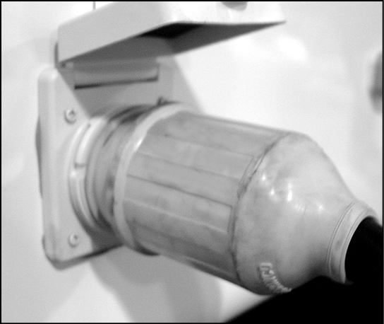
If you have 50-amp service, your power cord will look like this typical 50-amp power cord, which attaches to the unit.
50-amp service is also 110-volt service, but it is capable of running up to 50-amps of load. Some people believe that 50-amp service is the same as having 220-volts of AC power. Yes, 50-amps of service does have 220-volts, but only 110-volts is capable of being supplied to any part of your system at any given time. A unique, four-pronged power cord identifies 50-amp service, as two of the four prongs each carry 110-volts of AC power. Each of the 110-volt lines in a 50-amp cord supplies power to a designated part of your RV. In doing this, when 110-volt AC powered components are installed they can be put on separate power feeds according to how much amperage they draw. One example of this method consists of installing two air conditioners for use at the same time. Each one is powered by a different power supply feed with the 50-amp power cord; therefore they can both be used simultaneously.
|
|
|
MAKE SURE YOUR POWER SUPPLY (SHORELINE HOOKUP) IS PROPERLY GROUNDED! IF YOUR POWER SUPPLY TO THE TRAILER IS NOT GROUNDED YOU WILL EXPERIENCE A DANGEROUS SHOCK WHEN STANDING ON THE GROUND AND TOUCHING A METAL PORTION OF YOUR TRAILER! USE A CONTINUITY TESTER TO ENSURE PROPER POWER SUPPLY! |
|
|
|
DO NOT USE AN EXTENSION CORD WTH A CURRENT RATING LESS THAN THE AMPERAGE YOUR RV REQUIRES. EXTRA EXTENSION CORDS REDUCE THE AMPERAGE AND VOLTAGE BEING SUPPLIED TO THE RV AND MAY CAUSE DAMAGE TO ELECTRICAL COMPONENTS, INCLUDING THE SHORELINE CORD. |
|
|
IF YOU TRAVEL TO AN RV PARK THAT DOES NOT OFFER THE APPROPRIATE AMP SERVICE YOUR COACH REQUIRES, YOU WILL HAVE TO USE AN ADAPTER TO HOOK UP TO SHORE POWER. USE OF AN ADAPTER IS NOT RECOMMENDED, BUT MAY NOT BE AVOIDABLE. WHEN USING AN ADAPTER, REMEMBER THAT YOUR COACH WILL NOT HAVE SUFFICIENT POWER TO RUN AS MANY OPTIONS AS WITH FULL-AMP SERVICE. YOU MAY BE ABLE TO RUN BOTH YOUR AIR CONDITIONERS FOR A LIMITED TIME: HOWEVER, THIS WILL CAUSE DAMAGE TO BOTH YOUR AC UNITS AS WELL AS OTHER COMPONENTS BY OPERATING THEM WITH INSUFFICIENT POWER. |
AMP Usage
Listed below are components that might be used in Breckenridge vehicles and the typical maximum amperage draw each one has. This chart may help you decide which components you can safely use for an extended period without damage.
|
Components Roof air conditioners (each) Electric water heater Microwaves Hair dryer TV DVD Charger Refrigerator 110-volt lamp |
Amperage 15 12 12 8 4 5 14 3.5 1.0 |


Circuit Breakers
Circuit breakers protect the circuits in the vehicle. If you trip a breaker, turn off the appliance and reset the breaker. If the breaker continues to fail, contact your nearest dealer.
|
|
|
NEVER REPLACE CIRCUIT BREAKERS OR FUSES OF HIGHER CURRENT RATING THAN THOSE ORIGINALLY INSTALLED. THIS COULD OVERHEAT THE WIRING AND START A FIRE, POSSIBLY RESULTING IN PROPERTY DAMAGE, PERSONAL INJURY OR LOSS OF LIFE. |
110-Volt System
This is supplied by plugging the power cord into an outside 110-volt receptacle. It furnishes current to 110-volt roof air conditioners, refrigerator and all internal 110-volt receptacles. It also supplies power for the 12-volt trailer system through the converter.
The 110-volt circuits are protected by resettable circuit breakers, similar to the ones you would find in your home. Depending on your recreational vehicle the number of 110 volt appliances available, the circuit panel may have a 50 amp main or a 30 amp main breaker. All breakers are labeled for what appliance they protect and maximum amperage for the circuit breaker.
Your bathroom, kitchen and exterior receptacles are protected by a highly sensitive device known as a “Ground Fault Interrupter”, which is designed to sense the slightest electrical “short” at those receptacles and instantly disconnect the current before a person can be injured.
This device protects against fault currents only. It does NOT protect against over current.
|
|
The GFI receptacle is located in the bathroom; it should be tested at least once a month for maximum protection. To test the GFI receptacle push the TEST button. The RESET button will pop out. Power is now off at the outlets protected by the RESET button during the test and indicates the device is functioning properly. If the RESET button does not pop out when testing, do not use any outlets on this circuit. Protection is lost. Call your dealer if this device malfunctions. After a successful test, restore power by pushing RESET. Your test is complete when the RESET button stays pushed in. |

|
This connection is for low-voltage battery or direct current only. Do not connect to 120 or 240 volts ac. |
Monitor Panel (If Applicable)
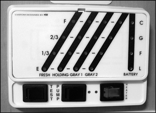
Your vehicle has a monitor panel that can provide you with important information about various systems on the RV. This panel also houses the water pump switch.
This monitor panel will give you information including:
- How much potable (fresh) water remains.
- How full your black (sewage) tank is.
- How full your gray (waste water) tank is.
|
|
THE MONITOR PANEL WILL GIVE FALSE READINGS IF THE SENSORS IN THE HOLDING TANKS ARE COVERED WITH DEBRIS. CLEAN YOUR WASTE HOLDING TANKS FREQUENTLY WITH APPROVED TREATMENTS. |
The possibility of fire exists in all areas of life, and the recreation vehicle life-style is no exception. Recreational vehicles are complex machines. They are made up of many materials, some of which are flammable. Like many hazards, the possibility of fire can be minimized. This is done by recognizing the danger and practicing common sense safety and maintenance habits. For safety reasons, your unit is furnished with both a fire extinguisher and a smoke alarm.
Fire Extinguisher
The fire extinguisher is rated for Class B (grease, gasoline, diesel fuel, flammable liquids) and Class C (electrical) fires. These are the most common types of fires in vehicles. Read the operator’s manual and the instructions on the fire extinguisher. Be sure to know how and when to use the extinguisher and where it is located.
Fire extinguishers are mechanical, pressurized devices. Care must be exercised when they are handled. They must be maintained as the operator’s manual instructs for proper and safe operation. The extinguisher should be inspected at least once a month. More frequent inspections may be required if the extinguisher is exposed to the weather or the possible tampering. Do not test the extinguisher by partially discharging; doing this will cause a loss of pressure.
If a fire occurs in the vehicle, evacuate the vehicle as quickly and as safely as possible. Consider the cause and the severity of the fire and the risk involved before trying to extinguish it. If the fire is major or fuel fed, move away from and stand clear of the vehicle and wait for emergency assistance to arrive.
|
|
|
TEST SMOKE DETECTOR OPERATION AFTER VEHICLE HAS BEEN IN STORAGE, BEFORE EACH TRIP, AND AT LEAST ONCE PER WEEK DURING USE. FAILURE TO COMPLY COULD RESULT IN FIRE OR SERIOUS INJURY. |
Smoke Detector
The battery-powered smoke detector is mounted on the ceiling in the living area of the unit. Read the operating instructions for details on the testing and care for this important safety device. Test the smoke detector after the unit has been in storage, before each trip, and at least once a week during use. The detector should never be disabled because of nuisance or false alarm from cooking smoke or a dusty furnace. Ventilate the unit with fresh air and the alarm will shut off. Never disconnect or remove the battery from the smoke alarm. The battery should be replaced no less than once a year or when the low battery signal sounds.
|
|
|
TEST SMOKE ALARM OPERATION AFTER VEHICLE HAS BEEN IN STORAGE, BEFORE EACH TRIP, AND AT LEAST ONCE PER WEEK DURING USE. FAILURE TO COMPLY MAY RESULT IN SERIOUS INJURY. |
|
EXIT |
Emergency Exit Window
Throughout the unit, there are Emergency Exit (egress) windows. These windows are designed to be used as an additional exit in emergency situations. It can be identified easily by the red handle and red “EXIT” label. To open the egress window, familiarize yourself and occupants with proper procedure.
There should be two paths of escape from each sleeping area. Familiarize yourself and occupants with these paths and the location of the exits.
Furnace
The furnace utilizes a sealed combustion system, which means the combustion chamber is completely sealed from the inner atmosphere of your vehicle. Combustion air is drawn from the outside and combustion products are expelled outside through a vent.
Carefully read and follow the lighting and operating instructions from the furnace manual supplied with the unit.
New furnaces sometimes emit smoke and an odor when first used due to paint burning off the heating chamber. Do not mistake this for a malfunctioning furnace. You may want to open the windows during the initial breaking in of the furnace.
Thermostat readings may not always be a true indication of temperature throughout the living space. Use these readings as a guide to obtain the most comfortable level for you.
|
|
|
DO NOT STORE COMBUSTIBLE MATERIAL IN THIS AREA. FAILURE TO COMPLY COULD RESULT IN A FIRE OR PERSONAL INJURY. |
|
|
|
IF YOU SMELL GAS:
|
|
|
|
A warning label has been located near the LP gas container. DO NOT FILL CONTAINER(S) TO MORE THAN 80 PERCENT OF CAPACITY. Overfilling the LP gas container can result in uncontrolled gas flow, which can cause fire or explosion. A properly filled container will contain approximately 80 percent of its volume as liquid LP gas. Safety regulation prevents filling over 80 percent. |
|
|
|
Portable fuel-burning equipment, including wood and charcoal grills and stoves, must not be used inside the recreational vehicle. The use of this equipment inside the recreational vehicle may cause fires or asphyxiation. |
|
|
|
Storage of LP gas containers, gasoline or other flammable liquids inside your vehicle – even for short periods of time – presents a risk of fire and/or explosion. All flammable liquids should be stored safely in a well-ventilated area outside your vehicle and in proper containers. |
|
|
|
LP gas regulators must always be installed with the diaphragm vent facing downward. Regulators that are not in compartments have been equipped with a protective cover. Make sure that the regulator vent faces downward and that the cover is kept in place to minimize vent blockage which could result in excessive gas pressure causing a fire or explosion. |
|
|
|
All pilot lights, appliances and their igniters (see operating instructions) shall be turned off during refueling of motor fuel tanks and/or propane containers. Failure to comply can result in death or serious injury. |
Liquid Propane (LP) gas, when properly handled, is a clean burning, dependable fuel for all your LP gas appliances. The LP tank or tanks mounted on your unit contain liquid under high pressure. The liquid vaporizes into a gas and passes through the regulator which automatically reduces the gas pressure. The low pressure gas is then distributed to the appliances. The arrow on the automatic gas regulator will always point to the gas tank in service. When the red flag appears in the inspection glass this indicates that the tank is empty. The arrow should be turned to allow the full tank to pressurize the system and the empty tank should be filled as soon as possible.
Each tank has an automatic eighty percent stop-fill valve that allows space in the tank for vapor expansion. The high pressure vapor in the tank is reduced in two stages as it makes its way to your appliance. The tank pressure will vary with temperature and altitude, but it may be in the range of 100 to 250 pounds per square inch (psi) or more. It is reduced by a pressure regulator to about 12 psi in the first stage and then to about 6.35 ounces in the second stage. The 6.35 ounces can also be expressed as 11 inches of water column.
The LP gas system is designed and built to rigid standards and tested before leaving the factory. Your dealer also tests the system prior to customer delivery.
|
*NOTE |
|
YOUR DEALER IS RESPONSIBLE FOR A THOROUGH LP GAS SYSTEM CHECK PRIOR TO DELIVERY. DO NOT ACCEPT THE UNIT UNTIL THIS CHECK HAS BEEN COMPLETED. |
Except for simple maintenance and occasionally tightening a connection, you should take your unit to an authorized dealer for LP gas problems. An authorized LP supplier should always fill the LP gas tank.
|
|
|
LP-GAS CYLNIDERS SHALL NOT BE PLACED OR STORED INSIDE THE VEHICLE. LP-GAS CYLINDERS ARE EQUIPPED WITH SAFETY DEVICES THAT RELIEVE EXCESSIVE PRESSURE BY DISCHARGING GAS TO THE ATMOSPHERE. FAILURE TO COMPLY COULD RESULT IN DEATH OR SERIOUS INJURY. |
|
|
YOUR UNIT’S MANUFACTURER IS NOT RESPONSIBLE FOR PERSONAL INJURY OR PROPERTY DAMAGE RESULTING FROM IMPROPERLY MAINTAINED LP GAS APPLIANCES AND SYSTEMS. |
|
|
|
THIS GAS PIPING SYSTEM IS DESIGNED FOR USE WITH LP-GAS ONLY. DO NOT CONNECT NATURAL GAS TO THIS SYSTEM. SECURELY CAP THIS INLET WHEN NOT CONNECTED FOR USE. AFTER TURNING ON GAS, EXCEPT AFTER NORMAL CYNLINDER REPLACEMENT, TEST GAS PIPING AND CONNECTIONS TO APPLIANCE FOR LEAKAGE WITH SOAPY WATER OR BUBBLE SOLUTION. DO NOT USE PRODUCTS THAT CONTAIN AMMONIA OR CHLORINE. |
|
|
|
NEVER ADJUST THE REGULATOR YOURSELF. HAVE YOUR DEALER OR AN AUTHORIZED SERVICE TECHNICIAN MAKE ANY REQUIRED ADJUSTMENTS. |
Filling LP Gas Bottles
When your LP gas tank is empty, have it refilled as soon as possible. There are many LP refueling stations available. Many RV parks also have LP gas available. Caution your supplier not to over fill your tank. Room is required to let the liquid vaporize.
There are approximately 90,000 BTUs of heat produced from each gallon of LP gas. During extreme cold temperatures, check fuel tanks frequently to avoid running out of fuel.
Make sure that all burners and pilot lights are turned OFF prior to having a gas supplier refill your LP tank.
- Make sure the arrow on the cylinder selector is pointed to the full cylinder. (Verify the hose route to the full cylinder on a split system.)
- Close the valve on the empty cylinder and remove the hose from the valve. (NOTE: left hand thread).
- Loosen the clamp that holds the cylinder in place.
- Remove the cylinder and have it refilled.
- Slide the cylinder back in place and tighten clamp.
- Connect the left-hand hose and tighten securely
The 80 percent STOP FILL VALVE may close the valve before liquid appears at the 20 percent liquid level gauge, but if liquid does appear, stop filling immediately…the tank is filled to its LP capacity.
|
|
YOUR LP TANKS MUST BE KEPT FREE OF RUST AT ALL TIMES. IF RUST DOES DEVELOP, THE TANK SHOULD BE CLEANED COMPLETELY FREE OF THE RUST, PRIMED, AND PAINTED WHITE (OR SOME OTHER HIGHLY REFLECTIVE COLOR) WHICH WILL HELP TO REDUCE EXPANSION OF THE LP GAS BECAUSE OF HEAT. |
Do not use a wrench to tighten the service valve or the 20 percent gauge. They are both designed to be closed leak-tight by hand. If you cannot hand-tighten the valve, the valve may need repair or replacement. Consult your gas dealer.
|
|
|
IF YOU SMELL PROPANE
FAILURE TO COMPLY COULD RESULT IN EXPLOSION RESULTING IN DEATH OR SERIOUS INJURY. |
LP Gas Lines
The primary manifold is a black pipe located under the unit. Copper tubing with flare fittings are used as secondary lines running to the gas appliances. Should any lines ever rupture, NEVER attempt to splice them. A new line should always be installed. We recommend any LP gas line services be performed by your dealer or an authorized service technician. Always close main valve at LP tank when servicing any gas appliance. This prevents any gas leakage which could result in an explosion or cause serious bodily injury.
|
|
|
NEVER CHECK GAS LINES FOR LEAKS WITH AN OPEN FLAME. DO NOT CHECK FOR LEAKS USING AMMONIATED OR CHLORINATED HOUSEHOLD TYPE DETERGENTS. THESE DETERGENTS CAN CAUSE CRACKS TO FORM ON THE METAL TUBING AND BRASS FITTINGS. TAKE THE UNIT TO A QUALIFIED LP GAS SERVICE TECHNICIAN TO FIND AND REPAIR THE LEAK. KEEP THE TANK VALVE CLOSED AND ALL OF THE APPLIANCES TURNED OFF WHEN THE UNIT IS STORED. IF ANY OF THE LP GAS VALVES DO NOT CLOSE LEAK-TIGHT BY HAND, CONSULT A SERVICE TECHNICIAN. |
Although your LP gas system was thoroughly inspected for leaks before delivery, gas fittings can loosen from vibration during travel. Your LP gas system should be inspected at least every three months and before every trip. If a leak is suspected, check immediately!
Precautions and Recommendations
- Inspect LP fill valve for foreign material before refueling.
- Shut off tow vehicle and pilot lights when refueling gas tanks.
- Never check for gas leaks with an open flame match, etc.
- Visually inspect gas lines for any problem periodically.
- Have dealer inspect gas systems yearly and before and after long trips. Always have a qualified technician check and make any repairs in your gas system.
|
|
This gas piping system is designed for use of liquefied petroleum gas only. Do not connect natural gas to this system. Do not fill container(s) to more than 80 percent of capacity. Securely cap inlet(s) when not connected for use. After turning on gas, except after normal container replacement, test gas piping and connections to appliances for leakage with soapy water or bubble solution. Do not use products that contain ammonia or chlorine. |
|
|
|
ALL PILOT LIGHTS, APPLIANCES AND THEIR IGNITERS (SEE OPERATIONG INSTRUCTIONS) MUST BE TURNED OFF DURING REFUELING OF MOTOR FUEL TANKS AND/OR LP GAS CONTAINERS. |
|
|
|
THIS SYSTEM IS DESIGNED FOR USE WITH PROPANE ONLY: DO NOT CONNECT NATURAL GAS TO THIS SYSTEM. BEFORE TURNING ON PROPANE:
AFTER TURNING ON PROPANE:
|
Climate Differences
The appliances in your vehicle will not function if the LP gas does not vaporize. Propane will continue to vaporize down to -44 degrees F.
Propane has become the main type of LP gas used in RVs in recent years. Butane should not be used. The LP gas dealer will have the correct type or blend for his locale. If you plan on traveling from a warm climate to a cold climate, check with your local gas dealer to see if the blend he supplies is appropriate for the part of the country you plan on visiting.
Operation
To operate any LP gas appliance, the LP gas tank’s service valve must be OPEN. When first used, or after a refill, there may be some air in the gas lines that will escape when the range burner or similar gas valve is opened. The air may extinguish the match or igniter the first time or two you attempt to light a stove burner.
Also remember that when you close the tank’s service valve, some gas will remain in the lines. To completely bleed the lines of gas, close the tank valve and light the range burner. When the flame burns out, turn off the appliance.
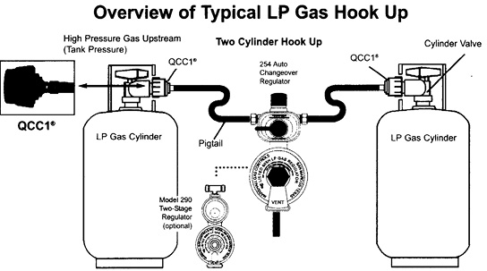
Regulator Pressure
Have the gas regulator checked at beginning of each season and whenever a problem occurs. Proper line pressure is 11 inches of water column. Your RV dealer or gas supplier can perform this needed check.
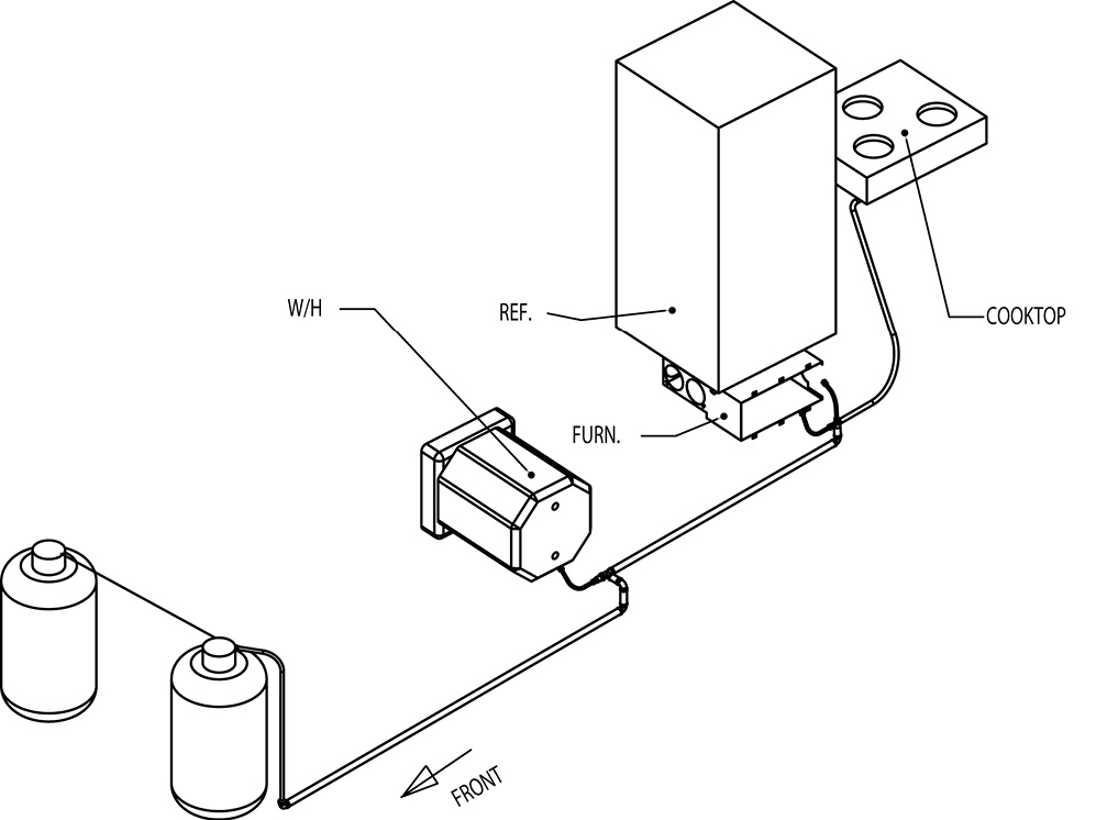
Gas Line Check
Check the gas line connectors and all other connections regularly. To check, turn OFF all burners and pilot lights. Open all doors and windows. OPEN the LP gas tank’s service valve and use soapy water or an approved leak detector fluid to test all line connections. Do not use products that contain AMMONIA or CHLORINE. The appearance of bubbles in the soapy solution indicates a leak. Tighten the connections with two (2) open-end wrenches until the bubbles stop. If this does not take care of the leak, contact your gas dealer. DO NOT OVERTIGHTEN.
Gas Tank and Regulator Freeze-Up
LP gas regulator freeze-up can be prevented if owners are aware of the causes. Freeze-up may be caused by one of the following: moisture in the tank, an overfilled tank or a greater vapor withdrawal demand than the tank can deliver at a particular temperature.
Freeze-up occurs more frequently in cold weather since liquid gas does not vaporize as quickly. This, along with a higher demand, can cause frost on the tank and regulator.
Be sure to have your LP gas supplier add ANHYDROUS METHANOL before filling the tank in cold weather.
Moisture may enter the tank in the LP gas through condensation if air is allowed to enter the tank through an open valve. This can be avoided by using moisture-free gas and keeping all tank valves CLOSED during storage. If moisture is present, have the tank purged by an authorized dealer and have him add the proper amount of ANHYDROUS METHANOL for your tank. An overfilled tank can allow liquid gas, rather than the needed vapor, to flow through the regulator. This can result in erratic regulator delivery pressure, improper appliance operation and possible frosting of the regulator and gas line. This can be avoided by following the procedures outlined in the Filling LP Gas Bottles section. Always contact your local gas supplier for current procedures.
Hose Replacement
The flexible LP gas hoses connected to your LP tank should be checked frequently for signs of deterioration and may need to be replaced every two to three years. Be sure to replace the hoses with approved and properly rated products.
Regulator Vent Maintenance
Since the LP gas regulator is equipped with a vent that allows the system to “breathe”, you must check it on a frequent basis to see that is does not become clogged. If dirt, sealant or corrosion clogs the vent, clean it with a toothbrush or similar device. At least once a year have your LP service provider check the regulator adjustment and operation.
LP Gas Detector
Liquid Propane (LP) gas is heavier than air and will settle to the lowest point of the room, which is generally on the floor of your coach. Because of this, the LP detector installed in your coach is located near the floor. The detector is also sensitive to other fumes, such as hair spray, which contain butane as the propellant. Butane, like propane, is heavier than air and will settle to the floor level where it may be detected.
The detector is equipped with a “sensor activation strip”. This strip must be removed for the detector to operate properly. This should have been done during the dealer’s pre-delivery inspection. Please check the detector to verify that the activation strip has been removed.
Please consult your LP detector User’s Guide for more detailed information
|
|
|
A WARNING LABEL LOCATED IN THE COOKING AREA REMINDS YOU TO PROVIDE AN ADEQUATE SUPPLY OF FRESH AIR FOR COMBUSTION. UNLIKE HOMES, THE AMOUNT OF OXYGEN SUPPLIED IS LIMITED DUE TO THE SIZE OF THE RECREATIONAL VEHICLE; PROPER VENTILATION WHEN USING THE COOKING APPLIANCE(S) WILL AVOID DANGER OF ASPHYXIATION. IT IS EXPECIALLY IMPORTANT TO ENSURE A FLOW OF FRESH AIR WHEN THE APPLIANCE IS USED FOR LONG PERIODS OF TIME. |
|
|
|
THIS IS NOT SAFE TO USE COOKING APPLIANCES FOR COMFORT HEATING. Cooking appliances need fresh air for safe operation. Before operation:
FAILURE TO COMPLY COULD RESULT IN DEATH OR SERIOUS INJURY. |
Fresh Water (If Applicable)
Fresh water is provided by filling the FRESH WATER TANK or by hooking directly to a city water connection. These sources supply water for the kitchen sink, shower, lavatory, toilet and water heater. Fill the FRESH WATER TANK using the connection shown on the left side of the photo below
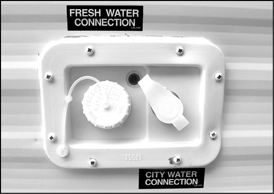
City Water and Gravity Fill Connections
Located on the exterior of the coach is the CITY WATER INLET. Connect a hose to a city pressurized faucet to the connection on the right of the photo above.
Fresh Water Tank (If Applicable)
UNLOCK the GRAVITY WATER FILL DOOR and use a hose or vessel to fill the water tank. Watch your monitor panel inside to determine when the tank is full.
|
Notice |
|
NEVER LEAVE YOUR COACH UNATTENDED WHILE FILLING THE FRESH WATER TANK! ALTHOUGH PROPER VENTING IS ALLOWED FOR OVERFLOW, THE WATER PRESURE CAN EXPAND THE TANK AND CAUSE SEVERE DAMAGE TO YOUR UNIT. |
|
Notice |
|
A PRESSURE REGULATOR SHOULD ALWAYS BE USED WHEN CONNECTING TO CITY WATER. EXCESSIVE WATER PRESSURE CAN DAMAGE LINES AND CONNECTIONS, CAUSING WATER DAMAGE TO YOUR RV. MAKE SURE WATER PRESSURE NEVER EXCEEDS 60 PSI. |
Sanitizing System
|
|
|
POTABLE WATER ONLY. SANITIZE, FLUSH AND DRAIN BEFORE USING. SEE INSTRUCTION MANUAL. FAILURE TO COMPLY COULD RESULT IN DEATH OR SERIOUS INJURY |
To assure complete sanitation of your potable water system, the following procedures are recommended for a new system. For one that has not been used for a period of time and for one which may have become contaminated:
- Prepare a chlorine solution using one (1) gallon of water and one-quarter (1/4) cup of household bleach (5% sodium hypochlorite solution). With tank empty, pour one (1) gallon of solution into the tank for each fifteen (15) gallons of tank capacity.
NOTE: As an option, several commercial solutions are available and should be used as directed on the package. - Complete filling of tank with fresh water. Operate all faucets to release trapped air. Pressurizing entire system with pump, if available, and turn off pump.
- Allow to stand for three (3) hours.
- Drain and flush with fresh potable water.
- To remove excessive chlorine taste or odor which may remain, prepare a solution of one (1) quart vinegar to five (5) gallons water and pour into tank. Allow solution to agitate in tank by vehicle motion (several days, if possible).
- Drain tank and flush with fresh potable water.
Fresh Water Lines
Vibration and flexing during traveling can cause pipes and fittings to work loose. Check all of the plumbing connections for leaks on a regular basis and not less than annually. If the water pump runs when all faucets are turned off, check for a leak. Be sure the drain valves are closed. Connections and the kitchen and bathroom faucets normally seal with hand tightening and a half turn with a wrench. If a fitting leak persists, disconnect completely and check for mineral deposits or foreign material on the sealing surfaces. Clean the surfaces thoroughly and reinstall the fitting. Take the coach to an authorized service center for repairs if the system continues to leak. Follow the winterizing instructions given on p.71 to reduce the risk of leaks caused by cracks from freezing pipes. Freezing damage can be extensive and expensive.
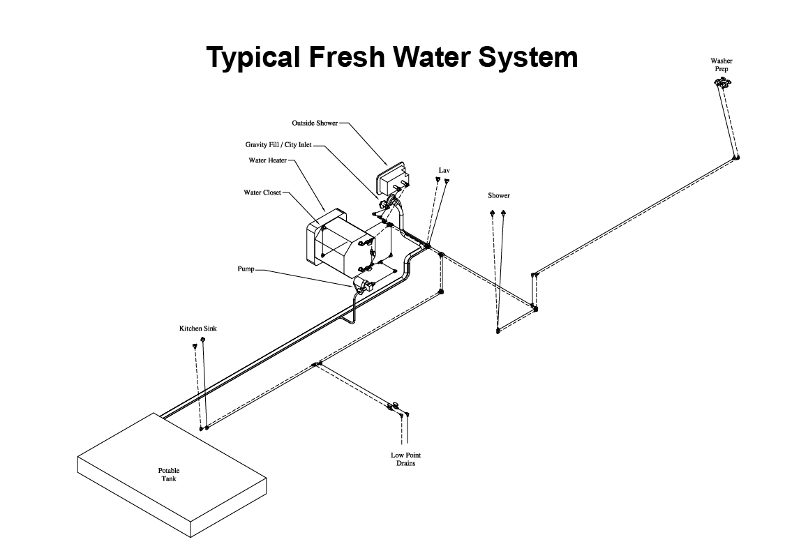
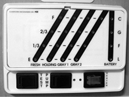
Water Pump
The RV water pump is a 12-volt DC appliance that is activated by a switch found on the monitor panel in the kitchen area. This switch is designed to activate the pump. This is called a demand system.
Turn the faucet on when you want water. If the pump fails to turn on when the switch is activated, check the fuse located in the converter. If the pump continues to operate whether the faucet is open or closed, check the water tank to see if it is empty and check to see if there is a leak in the system.
The water pump is self-priming and totally automatic, operating upon demand when water is required.
- Fill or partially fill freshwater supply tank.
- Open kitchen and bathroom faucets
- Turn on switch for water pump and allow it to fill the water lines and hot water heater.
- Close each faucet after it delivers a steady stream of water.
- Water pump should stop running after all faucets are closed.
- Pump should now run when faucet is opened and stop when faucet is closed.
When using the demand system and no water comes when a faucet is turned, use the following chart to correct the problem.
|
Situation |
Solution |
|
Pump Running – No Water |
|
|
Pump Doesn’t Run and no water pressure |
|
|
All water should be drained from the fresh water system when not in use for more than one (1) week. |
|
|
|
DO NOT RUN THE WATER PUMP WITHOUT WATER IN THE SYSTEM. ALWAYS KEEP THE PUMP SWITCH OFF WHEN THE SYSTEM IS EMPTY OR WHEN CONNECTED TO CITY WATER. RUNNING THE PUMP DRY CAN DAMAGE IT AND VOID THE WARRANTY. WHEN LEAVING YOUR CAMPER OR WHEN PULLING IT DOWN THE ROAD BE SURE TO TURN OFF YOUR WATER PUMP SWITCH. |
Waste Water System
The waste drainage system was designed to provide adequate and safe storage and/or disposal of waste materials. All of the materials used in the making of this system are tested by a nationally recognized testing laboratory. The drainage system uses plastic piping and fittings connected to the sinks, toilet, and holding tanks. This provides for their drainage to an outside termination. The unit should be reasonably level for best operation of the system. There are two separate waste systems. The gray water system is for waste water from the sinks and shower. The black water system is generally for sewage waste from the stool. Each tank has its own control valve, and both tanks drain through the sewer drain hose.
The drainage system also includes vents that carry odors caused by drain water and waste out of the RV, while also equalizing air pressure. Drain clean outs are provided to clean lines between fixtures and holding tanks.
Drainage P-traps
By code, all drains are equipped with P-traps to keep holding tank odors from entering the vehicle. If you detect a foul odor, which you believe is from your holding tanks, add water to all drains to ensure that your P-trap water hasn’t evaporated from long term storage or splashed out of the sink and shower drain while traveling. Places to add water include the kitchen sink, bathroom sink, shower/tub, wet bar sink, and the washer/dryer drain.
Black Water Holding Tank
The tanks should be emptied frequently, or as indicated on the monitor panel and especially before travel.
|
|
MOST STATES HAVE LAWS PROHIBITING EMPTYING SEWAGE ANYWHERE BUT AN APPROVED DUMPING STATION. |
While camping, it is normal practice to leave our GRAY WATER HOLDING TANK valve open if your campsite is equipped with sewer hook-up. NEVER leave the BLACK WATER TANK valve open while using the coach. Since the system utilizes gravity to empty, the BLACK WATER TANK will not drain properly unless it has sufficient liquid to help drain out the solids.
Dual Gray Holding Tanks
Some models are equipped with two gray holding tanks due to the floor plan. You must use the dump lever for each tank to empty the contents. Pulling the dump lever for one tank will not empty the other. The second holding tank has its own termination valve. The gray water holding tank is primarily used for drainage from the kitchen and bath sink and shower.
Emptying Holding Tanks
To empty the holding tanks, be certain that your RV is level since the process depends upon gravity. Remove the sewage drain hose from its storage location, below the docking center. Remove the cap from the termination outlet and connect the drain hose.

To drain either holding tank, pull out the TERMINATION VALVE (see photo on next page) by pulling out the dump valve slide handle. Close the valve after the tank has drained. Flush or pour about two gallons of water through the toilet when emptying the black tank and drain again. This flushes the tank and helps clean the drain hose. Repeat as necessary.

Follow the same procedure for the GRAY WATER HOLDING TANK(S). A repeat flush is not necessary. When the tank is empty, push the dump valve handle in until it seats. Remove the hose, wash and replace it in its storage location. Replace termination outlet cap.
|
|
DRAIN THE TOILET (BLACK) HOLDING TANK FIRST. |
|
|
|
FAILURE TO CLOSE THE GRAY/BLACK TANKS DURING PERIODS OF STORAGE MAY ALLOW P-TRAPS TO DRY AND ALLOW METHANE GAS OR OTHER COMBUSTIBLE GASSES TO BACK UP INTO THE UNIT, CREATING A RISK OF FIRE, EXPLOSION OR POISONING. |
Holding Tank Maintenance
Keep your tanks well flushed out when the vehicle is not in use. Allowing the tank to sit with any contents for more than a couple of days will ensure some sort of build-up on the monitor probes in the side of the tank and future monitor reading problems, even if this is the first time you have used your RV. One way to help flush them out is to drain them at the campground, then add approx. 10 gallons to each tank for the trip home.
Helpful Cleaning Hints
When camping there are a few things you can do to help facilitate the cleaning process later. First, you should always use some type of chemical additive in your holding tanks specifically designed for RV use. These types of chemical will break down the contents of the tank and help ensure good drainage. In addition, try using tissue designed for recreational vehicles. It will break down more than residential style tissues, and usually never clogs your drain valves.
Do’s and Do Nots of Holding Tank Use
DO – Clean the holding tank with an approved cleaner.
DO – Add a special chemical additive to sanitize and improve tank action.
DO – Guard the tank against freeze-up.
DO – Keep the waste water tank dump valves closed to allow the tanks to get as full as possible to facilitate drainage.
DO – Keep the dump valve closed and the drain cap in place to allow use of the system when not parked at a campsite.
DON’T – Put facial tissues, paper, automotive type antifreeze, sanitary napkins, diapers or household toilet cleaners in your holding tank.
DON’T – Put foreign objects in the system that could clog or damage it in any way.
DON’T – Travel with full holding tanks.
Holding Tank Flush System – “No Fuss Flush”
Your unit may be equipped with a waste holding tank flushing system. When draining your sewer tank, attach a water hose to the sewer spray hookup. Open the dump valve and let the tank empty. After the tank is drained, leave the gate valve open and open the water valve to allow water to spray inside the sewage tank. This will clean the inside of the tank of any debris that may be left inside the tank. After this is done, disconnect the water hose and close the gate valve.
|
|
|
DO NOT USE THE SAME HOSE FOR THE NO FUSS FLUSH THAT IS USED FOR FILLING THE FRESH WATER TANK. |
Refer to the individual manufacturer’s owner’s manual for additional operating and safety instructions on the following equipment.
Microwave Oven
The microwave is no different than that found in your home. It relies on 110-volt power for operation and should never be used while driving down the road. Read over the microwave oven’s owner’s manual to find all the information on its operation and cleaning.
Propane Appliances and Equipment Maintenance
Follow the instructions and warnings noted in the appliance and equipment owner’s manual as well as the ones listed below:
- Annual maintenance should be conducted on the propane appliances and equipment by an authorized dealer or repair facility.
- Insects can build nests in the burners of the various appliances and equipment. The burner and burner orifice of the propane appliances and equipment should be cleaned out by an authorized dealer or repair facility anytime circumstances or conditions warrant, but no less frequently than on an annual basis.
|
|
IT IS NORMAL FOR THE REAR COIL AREA OF YOUR REFRIGERATOR TO BE HOT. BE CAREFUL WHEN CHECKING THIS AREA TO MAKE SURE PROPER AIRFLOW THROUGH THE REAR VENT IS NOT OBSTRUCTED. |
Furnace
Your RV is equipped with a force-air furnace similar to the type found in most homes with the exception that it may be fueled by LP gas. Each unit is equipped with a wall mounted thermostat that controls the temperature. An operating manual for the furnace is included in your owner’s packet.
The furnace is designed to have un-obstructed airflow from all its vents, including interior and exterior. If any vent is blocked, the furnace may shut itself off.
The furnace igniter is powered by your 12-volt battery system. If the system battery is low, the furnace blower will come on; however the furnace will not ignite. Make sure your have sufficient battery power before operating the furnace.
Your furnace is designed to sustain a desired temperature in the vehicle at most times. Due to varying weather conditions, the furnace may not be able to keep up with sub-freezing tempteratures. The amount of occupants and the position the RV is parked may help or hinder the furnace’s ability to keep up with freeze conditions. Consult the furnace owner’s manual for more information
|
|
|
DO NOT SUPPLEMENT THE FURNACE WITH ANY PORTABLE FUEL-BURNING APPLIANCE FOR HEATING THE INTERIOR OR THE VEHICLE. THESE APPLIANCES ARE NOT SAFE. ASPHYXIATION/CARBON MONOXIDE POISONING IS POSSIBLE IN ANY WELL SEALED SPACE AND CAN RESULT IN SERIOUS PERSONAL INJURY OR LOSS OF LIFE. |
Air Conditioner (If Applicable)
Many vehicles are equipped with a roof air conditioning system that works with electrical power from either a shore line or a portable generator.
Air conditioners are capable of cooling air a maximum of 18 to 22 degrees below ambient temperature in a 50% humidity environment. As the humidity goes up, the cooling difference goes down. If the temperature inside your coach is 100 degrees when you turn on the air conditioner, it will only put out 80 degrees. Eventually the air inside the coach will cool, and as it cools, the air put out by the air conditioner will cool also. However, when starting out at 100 degrees, this cooling could take several hours before it reaches your desired temperature. Therefore, if you know the weather will be hot, turn your air conditioner on early.
The two most common complaints with roof air conditioners are they won’t turn on at all, or when they do turn on, they won’t put out cold air.
Thermostat Operation
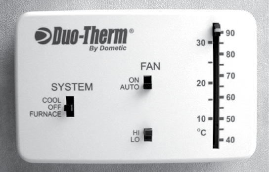
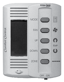
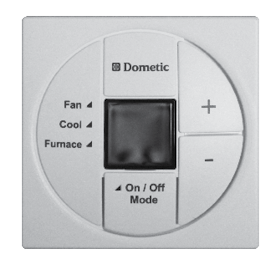
Cool Operation
- Set System button to Cool.
- Set slider to desired temperature.
- Set desired fan speed (Hi or Low).
- Set Fan operation (Auto cycles fan with compressor, or On runs fan constantly).
- A/C runs until desired temperature is reached.
Furnace Operation
- Set System button to Furnace.
- Set slider to desired temperature.
- Fan controls have no function for furnace operation.
- Furnace runs until desired temperature is reached.
Electric Ceiling Fan Operation
The ceiling fan used in your coach is designed to ventilate the interior when cooking or if the use of your air conditioner is not desired. If used properly the roof fan can cool the interior by as much as 15 degrees within a short period of time. When used, the fan pulls hot air from high inside the coach and will pull fresh air from an open window. This fan is usually controlled by a wall-mounted thermostat (some models have a thermostat built right on the fan), which must be turned on and adjusted to your desired temperature before use. The wall-mounted thermostat is not the same that is used for the furnace or air conditioners. Please review the supplied fan owner’s manual for additional operating instructions.
To keep condensation from accumulating open the vent lids slightly to help the air circulate. Condensation occurs naturally from fluctuations in interior and exterior temperatures, humidity and dew point changes, showering and cooking.
To clean the screen, remove the screws holding it in place. Wash the screen using a non-abrasive soap and water. Re-install the screen and tighten the screws.
Direct the airflow by slightly opening the windows(s) on the shaded side of the trailer to obtain the maximum air flow, especially on hot, sunny days. Close all the roof vents. The area between the open window(s) and the Rain Sensor fan supplies the maximum air flow and provides the most comfort.
|
|
DO NOT LEAVE ANY VENT COVER OPEN WHILE THE TRAILER IS IN MOTION, STORED OR UNATTENDED FOR EXTENDED PERIODS OF TIME. HIGH WINDS OR OTHER UNUSUAL CONDITIONS OR OBSTRUCTIONS MAY DAMAGE THE COVER AND PREVENT CLOSING. LEAKAGE COULD RESULT CAUSING SERIOUS DAMAGE. |
Water Heater
The water heater is accessed by a panel on the outside of the vehicle. Turn on the hot water faucet at the galley sink to see if the tank is full. Before operating any gas appliance, make sure the valve on the gas tank is open. Your unit may be equipped with a tankless water heater. Consult manufactuerer’s owner’s manual for operation

|
|
|
ALL PILOT LIGHTS, APPLIANCES AND THEIR IGNITERS (SEE OPERATING INSTRUCTIONS) MUST BE TURNED OFF DURING REFUELING OF MOTOR FUEL TANKS AND/OR LP GAS CONTAINERS. |
This section covers the basic operation and care of various equipment found in your Breckenridge. More detailed information as well as CAUTION or WARNING instructions about specific equipment may be found in each product manufacturer’s manual. Optional equipment will also be discussed in this section which does not apply to all vehicles.
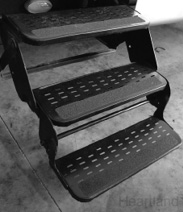
Entry Step (If Applicable)
Entry steps folds under the vehicle when traveling. To extend step, pull assembly out from underneath the vehicle. Bottom step is folded over second step – roll bottom step out and down after step assembly is extended. To store steps, fold bottom step up over second step and push assembly underneath the vehicle.
Lubricating the Mechanism: Lubricate the mechanism every 30-60 days. Carefully clean the area around the pivot points (the rivets involved in the motion of the mechanism). After cleaning, lubricate the pivot point between the pelt (to pinpoint this area locate the washer between the parts). An automotive grade, non-staining lubricant is recommended.
Covering Nicks & Scratches: Seal a nick or scratch with automotive grade primer to prevent rust. Once the nick or scratch has been sealed, cover the damaged area with an automotive grade or high-gloss paint.
|
|
|
TO PREVENT THE POSSIBLITY OF SLIPPING ON THE ENTRY STEP AVOID EXCESS LUBRICANT ON THE SURFACE OF THE ENTRY STEP ITSELF. CAREFULLY CLEAN THE ENTIRE ENTRY STEP AFTER LUBRICATING THE MECHANISM. |
|
|
SILICONE LUBRICANTS AND WD-40 ARE NOT RECOMMENDED AS THEY TEND TO EVAPORATE AND DRY THE MATED SURFACES WHICH LEAVES THEM VULNERABLE TO THE ELEMENTS. |
|
NOTICE |
|
IF THE VEHICLE IS TRANSPORTED WITH THE STEP IN THE EXTENDED POSITION THERE IS POSSIBILITY OF CAUSING MAJOR DAMAGE TO BOTH THE STEP AND THE VEHICLE. |
Entry Door
The door uses two separate locks for personal safety and security. The door handle incorporates a primary and secondary latching system. One locking system is the door handle and the other is a dead bolt. However, keeping the entry door in good operating condition requires some routine maintenance. The following adjustments can help maintain the entry door performance.
The position of the striker plate may change over the course of time and settlement of the recreational vehicle. The setting may need to be adjusted to insure that the door operates smoothly and efficiently. To adjust the strike plate, loosen the two screws holding the plate to the jamb system. Move the plate in or out as needed to obtain a proper seal closing force. Retighten the screws.
|
NOTICE |
|
IF SCREWS ARE LOOSE ON THE OUT-SWING DOORS, THE BACKER PLATE WILL RELEASE AND DROP DOWN INTO THE DOOR JAMB. SHOULD THIS HAPPEN, REPLACE THE SHORT SCREWS WITH A SCREW THAT IS LONG ENOUGH TO GO THROUGH THE JAMB SYSTEM AND INTO THE FRAME WORK OF THE SIDEWALL. |
The locking cylinder requires slight lubrication on an annual basis, or as needed. Use powdered graphite, not a petroleum product which will gum the cylinder and inhibit smooth operations. The upper lock is the dead bolt, the lower lock is the privacy lock. Applying a light coating of white lithium grease to the face of the lock bolt helps in retaining a smooth close. The hinges for the door require slight lubrication annually, or as needed, with a high-quality, dry spray lubricant.
The screen door can be adjusted to sit flush in the door jamb. This requires two separate adjustments to be performed. The first adjustment made is at the screen door latch/catch itself. Loosen the two screws holding the latch to the door to permit vertical adjustment. Move the latch far enough to catch on the striker mounted at the door frame. Tighten both screws. The striker mount on the door frame permits horizontal adjustment. Again, loosen the two screws holding the striker assembly. Move the striker to center the latch and tighten the screws in place.
It is a simple procedure to replace the sliding cover. Place the slider in the center. Pull from the center of the slider; it will bow enough to allow easy removal. To re-install, reverse this procedure. Install the upper left corner first and pay attention to the location of the stop tabs.
Sofa Bed Conversion (Optional)
The sofa will convert easily into a bed. Before converting the sofa to a bed clear the area of obstruction.
Sofa to Sleeper: raise the sofa seat base until the seat base and backrest form a V shape by lifting up from the center of the sofa just below the seat cushions, push down on the seat base until the seat base and back rest are flat.
Sleeper to Sofa: Lift the seat base up until seat and back rest are in a V shape and push down on the seat base.
Roll Over Dinette & Bed (Optional)
The dinette can be used as a bed or a dinette. When not in use the dinette is stored and secured to the sidewall. There are two dinette sections used, one for each side. A fold up portable table is used and should be properly stored when in transit.
To Use The Bed: Remove straps from each section and fold all legs out, lower bed sections and fold cushions out to form the bed.
To Use The Dinette: Remove retaining straps from each section and fold out bottom cushion legs of each section only, lower each section bottom cushion to rest on the legs and rotate inner cushions to form back rests.
Dinette Bed Conversion (Optional)
To convert the dinette into a bed: remove the tabletop from the leg supports and set aside, remove the leg supports from the base and store, slide the tabletop between the booth benches allowing it to rest on the guide rail and lay both seat cushions and back cushions together to form a mattress.
Storage – Under Bed (Optional)
To use the storage compartment located under the bed, lift up the bed by the front edge of the mattress platform. Gas struts hold the mattress and platform open.
|
|
FOR MORE DETAILED INFORMATION AND OPERATING INSTRUCTIONS, REFER THE TO THE MANUFACTURER’S MANUAL. |
Overhead Storage
The overhead storage is to be used for light weight items only.
Entertainment Center: AM/FM/CD/DVD Player
The entertainment center stereo system consists of AM/FM Stereo Tuner, CD/DVD Player and interior speakers.
|
|
FOR MORE DETAILED INFORMATION AND OPERATING INSTRUCTIONS, REFER THE TO THE MANUFACTURER’S MANUAL. |
Television Antenna (optional)
The television antenna is a manual crank up antenna with built in electronics that use 12 Volts DC to boost signal strength. Weak signals can be amplified by turning on the boost switch. The antenna and booster work together to provide the best possible picture for most situations. Certain conditions occur when no amplification is needed and the booster may make the picture worse.
|
|
DO NOT MOVE THE RECREATIONAL VEHICLE WITH THE ANTENNA RAISED. DAMAGE CAN OCCUR FROM LOW TREE LIMBS OR WIRES. |
|
|
|
BEFORE RAISING THE ANTENNA MAKE AN OUTSIDE VISUAL INSPECTION FOR ANY OBSTRUCTIONS OR OVERHEAD ELECTRICAL WIRES. DAMAGE TO THE ANTENNA, SEVERE SHOCK, PERSONAL INJURY OR LOSS OF LIFE CAN OCCUR FROM INADEQUATE CLEARANCE. |
To raise the antenna, rotate the crank handle clockwise to raise the antenna (about 14-15 turns). Pull down on the outside directional wheel and rotate the antenna until the best picture is obtained (the directional wheel is spring loaded).
To lower the antenna, pull down on the directional wheel and align arrows then rotate crank handle counterclockwise lowering antenna fully into the cradle. Make an outside visual inspection to ensure the antenna is properly stowed.
If your trailer is equipped with a slide out precautions must be taken before operation of the slide room.
- Make sure you have clearance on the exterior
- Make sure that all your interior items are clear.
- Make sure you have sufficient battery power.
- Press and hold the slide-out room switch in the OUT position. The slide-out room will move slowly to the out position. The drive motor will not stop automatically. To stop the slide-out room before reaching the OUT position, release the switch. To continue room movement, push and hold the switch. Release the switch to lock the room into position.
|
NOTICE |
|
CONFIRM THERE IS FIVE OR MORE FEET OF CLEAR SPACE OUTSIDE OF SLIDE-OUT ROOM TO THE OUT POSITION. CHECK THAT ALL CABINETS ARE CLOSED BEFORE EXTENDING OR RETRACTING THE ROOMS. |
|
NOTICE |
|
DIRT AND GRIT TRAPPED UNDER THE SLIDE COULD RESULT IN DAMAGE TO THE FLOOR. LEAVES, TREE LIMBS AND OTHER DEBRIS COULD DAMAGE THE SLIDE-OUT ROOF AND SEALS. CLEAN SLIDE-OUT ROOF BEFORE OPERATING. |
|
NOTICE |
|
SEVERE WEATHER CONDITIONS SUCH AS HIGH WINDS OR HEAVY RAIN MAY CAUSE DAMAGE TO AN EXTENDED SLIDE-OUT. |
|
NOTICE |
|
DO NOT EXTEND THE SLIDE ROOM IN SNOW, SLEET, ICE OR FREEZING RAIN. THERE MAY BE EXTENSIVE DAMAGE RESULTING FROM THE AWNING FREEZING. IN THE EVENT THE SLIDE-OUT ROOM IS EXTENDED IN SNOW, SLEET, ICE OR FREEZING RAIN CONDITIONS, CLEAR THE AWNING AND ENSURE FREE MOVEMENT PRIOR TO RETRACTING THE SLIDE ROOM. |
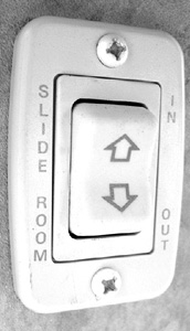
Retracting Slide Outs
- Make sure you have clearance on the interior.
- If applicable – clean the floor.
- Remove any debris from the top of the slide-out room.
- Press and hold switch in the IN position. To stop slide-out room before it fully retracts, release the switch. To continue the room movement, push and hold the switch in. When the room is fully retracted, release the switch to lock into position.
Slide Out Awning (Optional)
The slide out awning is automatic. When the slide-out moves in or out, the cover reacts to the slide-out direction. A fixed edge of the slide out cover is installed into an awning rail, mounted just above the slide out. A spring-loaded roller with special brackets mounts to the slide out. In a hard rain, the cover helps prevent water from penetrating the seal of the slide-out.
The slide out cover will extend automatically attaining full coverage when the slide out achieves maximum extension. The slide-out cover retracts automatically and rolls up to the travel position when the slide-out is completely closed.
|
|
WATER MAY POOL ON TOP OF THE EXTENDED COVER. AS THE SLIDE-OUT IS RETRACTED, THE WATER IS REMOVED. |

|
|
WHEN RETRACTING THE SLIDE-OUT, STOP THE ROOM ABOUT HALFWAY CONFIRM THAT THE FABRIC IS ROLLING PROPERLY BEFORE FULLY RETRACTING THE SLIDE OUT. |
Electric Slide Out Systems
Electrically operated slide out rooms utilize a gear drive to move in and out. Each guide ram on the underside of the room has its own gear, which is driven by a shared electric motor. Several different types of electric systems are used on Breckenridge products, depending on the model. But each is able to be operated by a hand crank in the event of a motor or power failure.
Slide Out Circuit Breakers
If attempting to move the slide and it is perceived that the electric motor has no power, inspect the breakers and fuses. If a fuse is blown you may need to replace it.
Slide Out Weather Seals
Frequently check all seals and gaskets on the slide out walls for proper fit and operation. The seals and gaskets should be coated with a silicone spray for easier operation and weather protection.
Inspect the condition of the slide tubes (not the hydraulic ram) under the slide out, and if needed, use bearing grease for ease of operation.
Although every attempt is made to have 100% air-tight seal, you will find that the best seal possible can be achieved with proactive maintenance and proper use.
|
|
|
xxx lbs. Max. load capacity Failure to comply with the load capacity could cause bed failure which may result in injury. Bed (s) must be stowed in the up position during travel. Elevated beds may present a fall hazard which may result in injury. Please consult the Owner’s Manual for more information regarding elevated beds and the use of bed rails. |
Standard Elevated Beds
Various Breckenridge products are equipped with standard built-in elevated beds or bed loft areas. These beds can be 4 feet or higher above the floor level and are often enclosed on one, two, or three sides and sometimes even partially on a fourth side. Because there are so many potential users and different types of elevated bed designs, elevated beds are not equipped with bed rails.
Use of Bed Rails
We feel that you, as the customer, are best equipped to determine if a bed rail system is necessary or best for you based on your intended uses, the actual users of the elevated beds, and the comfort level of the users.
For those customers who would prefer using an elevated bed with a bed rail, there are numerous bed rail styles, sizes, heights, and designs available, even in the style of bumpers, which can be purchased at various retail locations and/or on the internet.
When installing a bed rail please make sure that you follow the manufacturer’s installation instructions carefully and that you take in to account the size and height of the mattress (either originally installed by Breckenridge or later replaced by you) so that the rails are the appropriate height above the top of the mattress. This is important because residential mattresses differ in size from the RV mattresses originally installed by Breckenridge.
Please also make sure that the bed rail you select allows for adequate room to get in and out of the elevated bed after installation, especially in the event of an emergency.
Tips for Safe Usage:
- Please use sound judgment when allowing children to sleep in any style of elevated bed. Generally, it is not suitable for children under the age of 6 to sleep in an elevated bed or bed loft area.
- Discuss proper usage of any elevated bed with your children and make sure they are supervised if playing in the bedroom/sleeping area of the trailer with elevated beds. Please do not allow horseplay on or under the elevated beds and no items such as hooks, belts, jump ropes, or towels should hang from any part of the elevated bed.
- Place a night light in the bedroom/sleeping area so users can see at night when getting in and out of the beds.
- No more than one person should be in an elevated bed at once and make sure you follow the weight restrictions posted on the warning label near the beds.
Please refer to the Maintenance Schedule at the beginning of this manual.
Seals
The seals around doors, windows, vents and external seams must be checked every 3 months or change of season. If deterioration is noted, reseal the seams or seals with an approved sealant to prevent leaks. Your dealer can perform the resealing inspections and work for you. Your dealer is also able to inform you of the appropriate sealants to be used, if you prefer to do the job yourself. Sealants can be purchased from your dealer or manufacturer. Seals are not covered under warranty
|
|
Breckenridge, DOES NOT RECOMMEND THIS RV FOR USE IN THE WINTER UNLESS IT IS EQUIPPED WITH ADDITIONAL INSULATION AND PROPERLY SEALED UNDERBELLY. SEE YOUR DEALER OR CONTACT Breckenridge FOR MORE DETAILS. |
Rubber Roof (optional)
The rubber roof system should be cleaned periodically and inspected for tears or voids in the sealants (see maintenance schedule). When cleaning the rubber roof you only need to use a mild detergent, plenty of water, and a medium bristle scrub brush. Special cleaners are not necessary. You should check with the rubber roof manufacturer prior to using cleaners, coatings or sealants advertised to prolong the life of your rubber roof, as they are not necessary.
When cleaning your roof it is recommended that you use a long handled bristle brush and a steady ladder to reach all parts of the roof.
Lack of maintenance may allow mildew to form and discolor the rubber membrane. Although this may be unsightly, it is not cause for roof replacement. Simply use a scrub brush to clean as much as possible and touch up and areas of sealant that look suspicious. This is not covered under warranty.
Rubber Roof Repair
Small tears or punctures in the rubber roof membrane can easily be repaired and will have the same life span as the rest of the rubber roof. Most RV dealers carry rubber roof repair kits at a very nominal price. Please refer to your specific repair kit for proper applications.
Fiberglass Exterior Skin (Optional)
Wash the RV with a quality, mild soap. There are special fiberglass cleaners on the market and available at most RV dealers. DO NOT USE STRONG ALKALINE CLEANERS OR CLEANERS WITH ABRASIVES.
Waxing the exterior will further protect the outside surfaces. USE A WAX FORMULATED FOR FIBERGLASS. Follow the instructions found on the product label.
When washing and waxing the exterior of your RV, be sure to inspect all seams and trim for damaged or missing sealants. Occasionally during washing some sealants may be washed away, and harsh climates can accelerate the deterioration of sealants. As a guideline, inspect these areas four (4) times a year or whenever the RV is washed or waxed, whichever is more frequent. Unsealed areas can lead to expensive structure repairs in the future.
The bonded fiberglass wall may show a “print through” of the inner structure supports and beams. This is normal and may be more evident in harsh climates.
Washing
The exterior of your new recreation vehicle is made of pre-finished aluminum, fiberglass,vinyl or log siding. Frequent washing and thorough cleaning is recommended to prevent damage to the vehicle finish caused by exposure to calcium chloride, road tar, tree sap, insects and other foreign material. Corrosive materials, such as those used for ice and snow removal and dust control, also accumulate on the underside of the vehicle. These materials should be removed by flushing the underbelly regularly with water, especially areas where mud and other foreign materials collect. The change of corrosion can be minimized by frequent washings of the vehicle.
Corrosion Protection
Your Breckenridge recreational vehicle has been designed to withstand normal environmental condition. But, the sand and salt used on the highways and the salt spray in the air near oceans can cause the metal components on your recreational vehicle to corrode.
To protect your recreational vehicle from this corrosion, it must be thoroughly cleaned as soon as possible after exposure to these elements. Washing the undercarriage with a high-pressure washer will remove the majority of the salt. But, this will not replace the paint that is literally sandblasted off the undercarriage by the road salt and sand. Sandblasted and corroded frame components must be refinished. This is not covered under warranty. This can be done with readily available rust preventative paint and undercoating. This is necessary to properly maintain your recreational vehicle.
Aftermarket undercoating processes are also beneficial in rust prevention. But, to remain effective, these treatments must be inspected and renewed annually as most undercoating agents can dry and peel with age.
Therefore, regularly scheduled inspections and maintenance are necessary to protect your recreational vehicle and its various components and fixtures from the elements and keep it corrosion-free.
In addition to maintenance, you should keep from storing your vehicle in grassy areas for long periods of time. The stagnant, moist air developed under the coach will speed up the corrosion process. Always store your vehicle on pebble, concrete or asphalt surfaces.
Awnings (optional)
Awnings installed on your trailer may have been added by your dealer. Proper use, care and maintenance procedures for awnings are included in the literature provided with the awning.
To open your main awning (Manual):
- Make sure that you have sufficient clearance from obstructions.
- Unlock the awning using the provided wand by pulling down the locking latch located on the top of the right awning arm. (if equipped)
- Unlock the travel lock on the awning arm (if equipped).
- Loosen the rafter arm knobs located in each awning arm.
- Using the wand, hook the loop hanging in the center of the awning and pull the awning completely out.
- Slide each rafter arm to the top of each awning arm and tighten the rafter knobs, make sure the awning fabric is not loose.
- Near the base of each awning arm is a flip-out lever/handle, which is also an awning arm slide lock. When the lever is flipped out, the awning arm can be slid up to raise the awning. Flipping the lever back down will allow the arm to lock.
- Your awning is now in place. You may choose to use anchor straps for extra support in windy conditions.
- For further details, see the awning manufacturer’s instruction manual.
To close the main awning:
- Flip the awning arm levers out and slide the awning arms back down, being careful not to let the awning drop down, as flipping the levers out will unlock the arm and allow it to slide down.
- Loosen the rafter arm knobs and slide the rafter arm as far down as it will go. Do not re-tighten the rafter arm knobs at this time.
- While holding the wand strap in the awning tube, push the awning main latch located on the top of the right arm to “locked”. BE CAREFUL! This will cause the awning to roll up if you don’t have a good hold of the awning tube strap.
- Holding the awning tube strap, allow the awning to roll up until you can use the wand in the strap. Using the wand, allow the awning to roll all the way up. Do not allow the strap to get rolled all the way in the awning fabric.
- Lock the awning arm travel latches.
- Re-tighten the rafter arm knobs located in each awning arm.
To open your main awning (Electric):
Press and hold the “Extend” button and the awning will automatically open. If the button is released the awning will stop. Continue pressing the button until awning is fully extended, then release.
To close your main awning (Electric):
Press and hold the “Retract” button and the awning will automatically close. If the button is released the awning will stop. Continue pressing the button until awning is fully retracted, then release.
|
NOTICE |
|
VISUALLY VERIFY THAT THE AWNING IS FULLY CLOSED An Awning left partially open can dislodge during high wind or travel |
|
|
|
BE SURE TO LOCK YOUR AWNING WHEN YOU CLOSE IT UP. FAILURE TO DO SO CAN RESULT IN SERIOUS PERSONAL INJURY OR LOSS OF LIFE. |
Awning Care
Be sure to clean off all debris as you roll up your awnings. Periodically wash off the awning fabric with a soapy water solution. Long term exposure to the sun may cause some fading over time, which is normal.
The fading of upholstery, carpet and other interior fabrics is generally caused by excessive sunlight. The drapes, blinds or shades should be kept closed when the vehicle is parked for an extended period of time to minimize fading. Normal deterioration of appearance items due to wear and/or exposure is not covered by the Breckenridge Limited Warranty.
Upholstery
Do not launder upholstery fabrics. Blot up stains promptly, before they set. Use an upholstery cleaner or mild solvent, depending on the stain. Never soak the fabric. Use as little water as possible. Blot rather than rub. Towel dry or have professionally cleaned.
Fabrics and Draperies
The fabrics that may be used in this vehicle for the bedspread, draperies, headboard and valances may be damaged by the use of improper cleaning products. Therefore, cleaning instructions for these items are DRY CLEAN ONLY. Water-based products are not recommended for cleaning the fabrics in your new unit. Most water-based household cleaning products are not formulated for use on these fabrics and may cause excessive shrinkage or fading.
Spills, spots or stains should be treated as soon as possible to avoid permanent damage. If a spill occurs, blot the fluid with a dry towel. Do not rub; rubbing may cause the liquid to “set” in the fabric. When attempting to clean a spot or stain, always start from the outside and work inward to avoid spreading it further. Some stains or soils are extremely difficult or impossible to be removed completely. These should receive immediate, professional attention. Spills, spots, stains or soils are the responsibility of the owner and are not covered by the Breckenridge Limited Warranty.
|
|
|
WHEN CLEANING THE UPHOLSTERY AND FABRIC IN THE UNIT, DO NOT USE LACQUER THINNER, NAIL POLISH REMOVER, LAUNDRY SOAPS, OR BLEACH. NEVER USE CARBON TETRACHLORIDE OR GASOLINE FOR ANY CLEANING PURPOSES. THESE ITEMS MAY CAUSE DAMAGE TO THE MATERIALS BEING CLEANED AND MOST ARE HIGHLY FLAMMABLE. FAILURE TO HEED THIS WARNING CAN RESULT IN SERIOUS PERSONAL INJURY OR LOSS OF LIFE. |
Carpet
Weekly vacuuming the carpet and fabrics throughout the vehicle is recommended to prevent an accumulation of dirt that can detract from the material’s appearance and shorten its life.
Countertops
Countertops are made of several materials that are highly resistant to normal spills and scuffs. Avoid regular use of abrasive pads and scouring powders which will dull the surface and make it more stain-prone. Confine knife blades and slicing to a chopping block (not supplied). Pots and pans straight from the oven or burner and irons should be placed on lined hot pads.
Appliances
Refer to the individual manufacturer’s owner’s manuals for proper care and cleaning of your appliances.
Walls
The walls should be cleaned periodically to maintain a new appearance. Use a non-abrasive cleaner with a soft cloth.
Ceilings
Use a damp cloth to clean the ceiling. Clean with a mild detergent in warm water. Never use a strong chemical. Excessive moisture may damage the ceiling.
Interior Finish
The interior surfaces are easy to clean with mild soap and damp cloth. Waxing is unnecessary. Stubborn stains may be removed with a spray cleaner. Scratches can usually be touched up with a good quality commercial furniture scratch remover.
Tub and Lavatory
Do not use steel wool, harsh abrasives or liquid cleaners with solvents. These surfaces are best cleaned with soap and water or dishwashing detergent and water.
Windows
The windows in your vehicle should open and close easily. If they become clogged with dirt, clean the mechanism with a small, stiff brush and spray with a silicone lubricant.
Doors and Drawer Fronts
The doors and the drawer fronts in your unit are made of high quality wood. They should be wiped off with a dust cloth and a good household cleaner.
Bedspreads
The manufacturer of the bedspreads recommends that the bedspreads not be washed, but professionally dry cleaned.
Winter Storage Recommendations
- Level the unit – front to rear and side to side.
- Remove bottled and canned goods and other items that could be damaged by freezing.
- Open all the faucets, valves and drains (including the toilet stool valve), water heater drain and line drain.
- Run demand pump till water stops flowing from faucets. Shut pump off immediately. Allow drains, faucets and valves to remain open for several hours or blow all extra water out with air. Be sure lines are empty.
- Close all faucets, valves and drains.
- It is a good idea to use an antifreeze solution for potable water for more positive protection. Do not use automotive type antifreeze.
- Before using vehicle again, you may want to sanitize the system.
- Completely drain holding tanks.
- Flush sink, shower-tub, lavatory and stool with a solution of hot water and dish soap. Allow to fully drain and flush with clean hot water.
- If possible, agitate the water in the holding tanks by driving a few miles, then drain tanks again.
- An alternate to step #9 is to use a chemical deodorant. Let mixture stand for a few days, then drain.
- Flush with fresh water, drain, and after tanks are dry, close dump valves and drain cap.
- Fill traps with an antifreeze approved for use in ABS plastic pipes. Normally, a cupful per trap is adequate. Do not use an antifreeze solution with an alcohol base.
- Turn the thermostat off.
- Put graphite in all the locks and lubricate all door hinges.
- Close all windows and roof vents.
Winterizing the Water Pump
With the water drained from the potable water tank, disconnect the water pump outlet hose and then turn the pump on to allow the remaining water to be pumped out (less than one cup).
|
NOTICE |
|
DRAINING THE WATER SYSTEM ALONE MAY NOT BE ENOUGH TO PROVIDE COMPLETE COLD WEATHER PROTECTION FOR AN RV UNIT THAT WILL BE STORED IN AN UNHEATED ENVIRONMENT WHERE TEMPERATURES DROP BELOW FREEZING. CONSULT YOUR DEALER FOR MORE INFORMATION ON THE BEST METHOD OF WINTERZING YOUR VEHICLE. |
If you desire, you can blow out the water lines with compressed air by opening all valves and placing the air nozzle into the system where the outlet hose has disconnected. Replace pump hose.
Water System Winterizing
- Drain the fresh water tank.
- Drain pipes by turning the water pump ON and opening a cold water faucet. Wait for the water flow to stop. Turn pump OFF. Leave faucets OPEN.
- Turn ON all faucets.
- OPEN the WATER HEATER drain valve located at the bottom of the heater (or remove plug). Let the water drain out. OPEN the heater SAFETY VALVE.
- Bypass the water heater.
- Use the siphon hose to add RV anti-freeze to your system, or use air-pressure to remove all remaining water from the system.
- After each faucet has been opened, drained, and closed, CLOSE the WATER LINE DRAIN VALVES.
- Drain the WASTE WATER HOLDING TANK.
- Double check that ALL WATER has been drained.
- Some water may remain in the fresh tank. This will not damage the tank.
|
|
|
DO NOT USE AUTOMOTIVE ANTI-FREEZE OR WINDSHIELD WASHER FLUID ANTI-FREEZE IN THE VEHICLE’S WATER SYSTEM. THESE CAN BE HARMFUL OR FATAL IF SWALLOWED. YOUR DEALER CAN PROVIDE YOU WITH SPECIAL ANTI-FREEZE THAT IS SAFE AND APPROVED FOR RV WATER SYSTEMS. ALWAYS FOLLOW MANUFACTURER’S INSTRUCTIONS FOR THESE ADDITIVES |
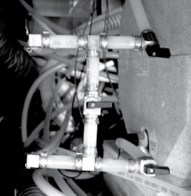
Water Heater Bypass
To bypass the water heater, turn the top and bottom valves off and the middle valves on.
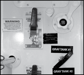
Water Heater Bypass
(One Valve System)
Effects
Your trailer was designed primarily for recreational use and short-term occupancy. If you expect to occupy the trailer for an extended period, be prepared to deal with condensation and the humid conditions that may be encountered. The relatively small volume and tight compact construction of modern recreation vehicles means that the normal living activities of even a few occupants will lead to rapid moisture saturation of the air contained in the trailer and the appearance of visible moisture, especially in cold weather. This is also not covered under warranty.
Just as moisture collects on the outside of a glass of cold water during humid weather, moisture can condense on the inside surfaces of the trailer during cold weather when relative humidity of the interior air is high. This condition is increased because the insulated walls of a recreation vehicle are much thinner than house walls.
Estimates indicate that a family of four can vaporize up to three gallons of water daily through breathing, cooking, bathing, and washing. Unless the water vapor is carried outside by ventilation, or condensed by a dehumidifier, it will condense on the inside of the windows and walls as moisture, or in cold weather as frost or ice. It may also condense out of sight within the walls or the ceiling where it will manifest itself as warped or stained panels. Appearance of these conditions may indicate a serious condensation problem. When using your trailer, you should at all times take necessary action to minimize the effects of excessive moisture and condensation. For tips on controlling condensation see the “Tips To Controlling Condensation” section.
|
|
Your trailer is not designed, nor intended, for permanent housing. Use of this product for long term or permanent occupancy may lead to premature deterioration of structure, interior finishes, fabrics, carpeting, and drapes. Damage or deterioration due to long-term occupancy is not considered normal, and may under the terms of the warranty constitute misuse, abuse, or neglect, and therefore void certain warranty protections. |
Ventilation and Moisture Control
You can reduce interior moisture condensation by taking the following steps:
- Ventilate with outside air. Partially open one or more roof vents and one or more windows to provide circulation of outside air into the interior. While this ventilation may increase furnace heating load during cold weather, it will greatly reduce water condensation. Even when it is raining or snowing, ventilation from outside will be far drier than interior air and will effectively reduce condensation inside the trailer.
- Minimize moisture released inside the trailer. Run the range vent fan when cooking and the vent fan (or open the bath vent) when bathing to carry water vapor out of the trailer. Avoid making steam from excessive boiling or use of hot water. Remove water or snow from shoes before entering to avoid soaking the carpet. Avoid drying overcoats or other clothes inside the trailer.
|
|
|
FIRE HAZARD DO NOT USE COOKING APPLIANCES FOR COMFORT HEATING. COOKING APPLIANCES NEED FRESH AIR FOR SAFE OPERATION. BEFORE OPERATION:
|
In addition to the hazards of toxic fumes and oxygen depletion, open flames add moisture to the interior air, increasing condensation. Do not use an air humidifier inside the trailer. Water put into the air by the humidifier will greatly increase condensation.
- Ventilate closets and cabinets. During prolonged use in very cold weather, leave cabinet and closet doors partially open to warm and ventilate the interiors of storage compartments built against exterior walls. The air flow will warm the exterior wall surface, reducing or eliminating condensation and minimizing possible ice formation.
- Install a dehumidifier. During prolonged, continuous use, a dehumidifying appliance may be more comfortable and effective in removing excess moisture from the interior air. While use of a dehumidifier is not a “cure-all”, and ventilation, storm windows and moisture reduction continue to be important, operation of the dehumidifier will reduce the amount of outside air needed for ventilation. Heating load on the furnace will be reduced and the interior will be less drafty.
|
|
|
DO NOT COVER EMERGENCY EXIT WINDOW(S). THIS WINDOW MUST BE LEFT ACCESSIBLE AT ALL TIMES FOR EMERGENCY EXIT. |
Dripping Ceiling Vents
During cold weather and even in short term occupancy, condensation frequently forms on ceiling vents and may even accumulate to the point of dripping onto the surfaces below. This is frequently misinterpreted as a “leaking” roof vent but is most often condensation drippage. Follow the preceding steps to control moisture condensation; protect surfaces with plastic sheeting until the moisture has dissipated.
|
|
|
UREA-FORMALDEHYDE IS USED IN THE PRODUCTION OF PARTICLE BOARD, HARDWOOD PLYWOOD, AND MOST PANELING. UREA-FORMALDEHYDE RESIN MAY RELEASE FORMALDEHYDE VAPORS INTO THE AIR, WHICH MAY CAUSE HEADACHES, AND IN SOME PEOPLE, EYE, NOSE, AND THROAT IRRITATION. FORMALDEHYDE MAY INTENSIFY SOME ALLERGIES OR UPPER RESPIRATORY PROBLEMS LIKE ASTHMA. PROPER VENTILATION SHOULD REDUCE THE RISK OF SUCH PROBLEMS. |
What are molds?
Molds are microscopic organisms that naturally occur in virtually every environment, indoors and out. Outdoors, mold growth is important in the decomposition of plants. Indoors, mold growth is unfavorable. Left unchecked, molds break down natural materials, such as wood products and fabrics. According to the Center for Disease Control, exposure to damp and moldy environments may cause a variety of health effects, or none at all. Some people are sensitive to molds. For these people, molds can cause nasal stuffiness, throat irritation, coughing or wheezing, eye irritation, or, in some cases, skin irritation. People with mold allergies may have more severe reactions. Immune-compromised people and those with chronic lung illnesses, such as obstructive lung disease, may get serious infections in their lungs when they are exposed to mold.
What factors contribute to mold growth?
For mold growth to occur, temperatures, indoor or outdoors, must be between 40 degrees and 100 degrees Fahrenheit and also have a source of moisture, such as humidity, standing water, damp materials, etc. Indoors, the most rapid growth occurs with warm and humid conditions.
How can mold growth be inhibited?
By controlling relative humidity, the growth of mold and mildew can be inhibited. In warm climates, use of the air conditioner will reduce the relative humidity. Vents are located in the bathing and cooking areas and constant use is advised during food preparation and bathing, even during colder weather. Additionally, opening a window during these activities will assist in ventilation. In extremely humid conditions, the use of a dehumidifier can be helpful.*
Frequent use of your RV or cleaning regularly is an important preventive measure. Further, any spills should be wiped up quickly and dried as soon as possible. Avoid leaving damp items lying about. On safe surfaces, use mold or mildew killing cleaning products. Check sealants regularly, and reseal when necessary to avoid water leaks. Proper preventive maintenance to the RV and its accessories, as described both in this manual and in accompanying literature, will provide the best protection to the RV.
For more information of controlling moisture in the RV, please read, “Tips to Controlling Condensation,” located in this manual.
*If using a dehumidifier, please read and follow all manufacturer instructions and recommendations to the use and cleaning of the dehumidifier.
Tips to Controlling Condensation
To avoid condensation problems, try to follow these tips to help alleviate excess moisture.
- Allow excess moisture to escape to the outside when bathing, washing dishes, hair drying, laundering, and using appliances and non-vented gas burners.
- Always use the vent hood when cooking.
- Keep the bathroom door closed and the vent or window open when bathing and for a period of time after you have finished.
- Do not hang wet clothes in the vehicle to dry.
- In hot weather, start the air conditioner early as it removes excess humidity from the air while lowering the temperature.
- Keep the temperature as reasonably cool during cold weather as possible. The warmer the vehicle, the more cold exterior temperatures and warm interior temperatures will collide on wall surfaces, thus creating condensation.
- Use a fan to keep air circulating inside the vehicle so condensation and mildew cannot form in dead air spaces. Allow air to circulate inside closets and cabinets (leave doors partially open). Please keep in mind that a closed cabinet full of stored goods prevents circulation and allows the exterior temperature to cause condensation.
- The natural tendency would be to close the vehicle tightly during cold weather. This will actually compound the problem. Simply put, you need to remove some of the warm air, and allow some cool outside air to get inside the vehicle, so the furnace will not recycle the humid interior air.
- Use fluorescent ceiling lights and minimize prolonged use of incandescent lights, which produce heat and contribute to condensation in the roof above the ceiling lights.
After you first purchase your new recreational vehicle and sometimes after it has been closed up for an extended period of time you may notice a strong odor and chemical sensitivity. This is not a defect in your recreational vehicle. Like your home, there are many different products used in the construction of recreational vehicles such as carpet, linoleum, plywood, insulation, upholstery, etc. Formaldehyde is also the by-product of combustion and numerous household products, such as some paints, coatings and cosmetics. However, recreational vehicles are much smaller than your home and therefore the exchange of air inside a recreational vehicle is significantly less than a home. These products, when new or when exposed to elevated temperatures and/or humidity, may “off-gas” different chemicals, including formaldehyde. This off-gassing, in combination with the minimal air exchange, may cause you to experience irritation of the eyes, nose, and throat and sometimes headache, nausea, and a variety of asthma-like symptoms. Elderly persons and young children, as well as anyone with a history of asthma, allergies, or lung problems, may be more susceptible to the effects of off-gassing.
Formaldehyde
Most of the attention regarding chemical off-gassing surrounds formaldehyde. Formaldehyde is a naturally occurring substance. It is also a key industrial chemical used in the manufacture of the numerous consumer products which we referred to above and used in the construction of recreational vehicles. Trace levels of formaldehyde are also released from smoking, cooking, use of soaps and detergents such as carpet shampoos, cosmetics, and many other household products. Some people are very sensitive to formaldehyde while others may not have any reaction to the same levels of formaldehyde. Amounts released decrease over time.
Ventilation
To reduce or lessen exposure to chemicals from off-gassing it is of utmost importance that you ventilate your recreational vehicle. Ventilation should occur frequently after purchase and at times when the temperatures and humidity are elevated. Remember off-gassing is accelerated by heat and humidity. Open windows, exhaust vents, and doors. Operate ceiling and/or other fans, roof air conditioners, and furnaces and use a fan to force stale air out and bring fresh air in. Decreasing the flow of air by sealing the recreational vehicle increases the formaldehyde level in the indoor air. Please also follow the recommendations contained in this chapter regarding tips to avoid condensation problems. Many of the recommendations contained in this chapter will assist in avoiding exposure to chemicals that off-gas.
Do Not Smoke
Finally, we recommend that you do not smoke inside your recreational vehicle. In addition to causing damage to your recreational vehicle, tobacco smoke releases formaldehyde and other toxic chemicals.
Medical Advice
If you have any questions regarding the health effects of formaldehyde, please consult your doctor or local health department.
Warranty Exclusion
CHEMICAL OFF-GASSING IS NOT A “DEFECT” IN YOUR RECREATIONAL VEHICLE AND IS NOT COVERED BY THE LIMITED ONE-YEAR WARRANTY. PLEASE FOLLOW THE RECOMMENDATIONS IN THIS SECTION TO ADDRESS THIS CONCERN.
|
This vehicle contains composite wood products that comply with the applicable California Code of Regulations section 93120.2(a) Phase 2 (P2) formaldehyde emission standards specified on the above date of manufacture. |